Nick do you connect all the black, white & black/white wires to orange wire signal/gnd or to chassis/gnd?
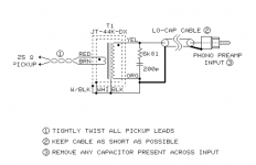
I see two whites and a black tied together going to the chassis ground, I also see a red and a brown going to the tip and ring of the RCA that the TT comes in. A yellow goes to the input stage signal side and an orange goes to the ground side.
Thanks, so chassis gnd are 1 white + 1 black + 1 black & white. Red signal input, brown gnd input, yellow signal output & orange gnd output.
SSHV2 damaged components list:
All 3 diodes
2 DN2540
1 SK117GR
1 KS1381
Please advice to use fuse: how many mA & volts to protect SSHV2?
All 3 diodes
2 DN2540
1 SK117GR
1 KS1381
Please advice to use fuse: how many mA & volts to protect SSHV2?
You cant fuse for volts but I think it should be good for 200 mA current. My guess is that it usually should be the mosfet that goes on overcurrent. The other comps for other reasons like wrong connections in/out, shorts etc.
Why the supply went out? You revisited any connections at the power side? To directly fuse input and output side for tests you would need 500V Fuses at little bigger mA than the CCS setting.
First I connected the step-up without the 47K load resistor, sounds OK both channels so I soldered the two 47K load resistors, connected and a big sound happened and no sound in both channels, once revised the first DN2450 was literally broken.....
I remember that can't get 500V fuses and you recommend me to put two 250V 0,1A in series separate a couple of centimeters of course before the SSHV2, is OK?
Last edited:
I don't see the how you load the SUT has anything to do with the power side. Has not even to do with some plate, its from grid to ground. Is there any low Ohm path you can find between B+ rail and signal ground that changes with that SUT secondary load resistor?First I connected the step-up without the 47K load resistor, sounds OK both channels so I soldered the two 47K load resistors, connected and a big sound happened and no sound in both channels, once revised the first DN2450 was literally broken.....
I remember that can't get 500V fuses and you recommend me to put two 250V 0,1A in series separate a couple of centimeters of course before the SSHV2, is OK?
They could be helpful, but if the event is so rapid and catastrophic I am afraid they will not be so fast to react. There is a weird reason to find why that happened first. Try the white+black+white/black on signal ground alternatively. Maybe something with the grounding created a mess.
![WP_20140501_014[1].jpg](/community/data/attachments/383/383614-be2289cfbcb5a29d9ac6f4d07e6e2d86.jpg?hash=viKJz7y1op)
![WP_20140501_016[1].jpg](/community/data/attachments/383/383623-2389aa74a9742f457ab3481b43085145.jpg?hash=I4mqdKl0L0)
![WP_20140501_017[1].jpg](/community/data/attachments/383/383633-a62006c626e3c16e8364a23e9c74e05e.jpg?hash=piAGxibjwW)
Maybe a big oscillation happened, the SMICA cap went parallel to the SUT secondary inductance // to the 47K between grid and ground. Tank resonance circuit. (Parallel Resonance and Parallel RLC Resonant Circuit). What are the red and green thicker wires? Signal carriers to the input tube?
Red input signal, green ground signal, both input Itch. Surely when not 47k load resistor used wired correctly....
Ground connections
Black/white/white+black are simple shields that are not circuit related, I can't see why they should make a difference to the supply.

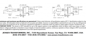
Jensen shows any as valid.
Attachments
...Anyway get them to signal ground too next time if there is some parasitic capacitance in play.
- Home
- Source & Line
- Analogue Source
- Valve Itch phono