Hi Marcel. I'm just getting some ducks lined up for my Valve DAC build.
To minimise any hum/noise I plan to use a regulated power supply for the E88CC filaments - 1.8A @ 6.3VDC. As the supply has a soft start feature I'll insert a link in place of the NTC and connect the DC supply to the board in the same way as the transformer winding would for the AC supply in the schematic.
I also plan to use a regulated supply for the 300V requirement - As I have one spare, I'll probably be using one of these;
21st Century Maida Regulator, Rev. 2.0
to configure this supply to deliver the corect voltage and current I need to calculate (actually the supplied spreadsheet does the calculation) some resistor values. Based on your comment that a 30VA transformer would suffice for this supply (the schematic shows 50VA) I deduce that the Valve DAC will draw about 50mA from the 300V regulated supply - does that sound about right?
I'll connect the regulated supply, with appropriate polarity, across where C126 would go and omit everything upstream of that.
I thought I might buy some of these 6N1Ps - Russian equivalents of E88CC - to get started.
https://www.diyaudio.com/forums/vendor-s-bazaar/240937-various-tubes-sale-24.html#post5874340
Ray
Last edited:
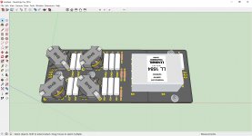
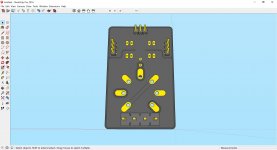
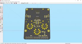
Hello Marcel and Ray,
some 3D views:
- FILTER board (RM8 custom Don audio; 2 layers)
- REF board (still need Pico socket and 85A2 3D models; 2 layers)
- DAC board started with routing (4 layers)
JP
some 3D views:
- FILTER board (RM8 custom Don audio; 2 layers)
- REF board (still need Pico socket and 85A2 3D models; 2 layers)
- DAC board started with routing (4 layers)
JP
Attachments


Hi Marcel. I'm just getting some ducks lined up for my Valve DAC build.
To minimise any hum/noise I plan to use a regulated power supply for the E88CC filaments - 1.8A @ 6.3VDC. As the supply has a soft start feature I'll insert a link in place of the NTC and connect the DC supply to the board in the same way as the transformer winding would for the AC supply in the schematic.
I already don't hear any hum with my AC heater supply, even when I turn the volume way up to listen to the noise floor. Of course a DC supply should also work fine, and the NTC is indeed not useful when you already have a soft start; in fact it would do harm by reducing the heater voltage below the recommended value. Keep in mind that the whole supply will be biased around -248 V with respect to ground by R137 and R138.
I also plan to use a regulated supply for the 300V requirement - As I have one spare, I'll probably be using one of these;
21st Century Maida Regulator, Rev. 2.0
to configure this supply to deliver the correct voltage and current I need to calculate (actually the supplied spreadsheet does the calculation) some resistor values. Based on your comment that a 30VA transformer would suffice for this supply (the schematic shows 50VA) I deduce that the Valve DAC will draw about 50mA from the 300V regulated supply - does that sound about right?
30 VA is for the complete valve DAC, so including the clock generation part and the neon lights that are not in the DSD-only version, and it is based on the rule of thumb that the RMS current through the transformer's secondary winding is about 1.6 times the DC output current with full-wave rectification - no idea what that rule is based on, but the few times that I checked it by simulation, it turned out to be close to the truth.
In any case, the DC current drawn from the -300 V in the DSD-only version is:
10 mA for the left-channel DAC
10 mA for the right-channel DAC
5.5 mA for the voltage reference
23.55 mA for the voltage divider R47...R141
Total: 49.05 mA, so quite close to your estimate!
I'll connect the regulated supply, with appropriate polarity, across where C126 would go and omit everything upstream of that.
Sounds good; again keep in mind that everything that is normally grounded is now at -300 V. The rate of change of the output voltage should be much less than 200 V/us to prevent potential latch-up issues in the 74AHCT74 flip-flops, but I'm sure that will be OK as long as you don't do any hot plugging.
I thought I might buy some of these 6N1Ps - Russian equivalents of E88CC - to get started.
https://www.diyaudio.com/forums/vendor-s-bazaar/240937-various-tubes-sale-24.html#post5874340
Ray
I use some old old stock valves that I bought at a second-hand market once.
Last edited:
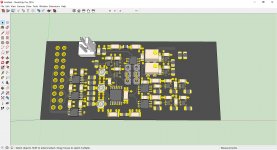
Hello Marcel and Ray,
some 3D views:
- FILTER board (RM8 custom Don audio; 2 layers)
- REF board (still need Pico socket and 85A2 3D models; 2 layers)
- DAC board started with routing (4 layers)
JP
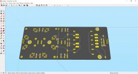
Looks very nice! Are the creepage distances for the DAC board sufficient?
Total: 49.05 mA, so quite close to your estimate!
Thanks Marcel, I'll configure the Maida regulator for 50mA. It will mean the Valve DAC will have an excellent, very low ripple, 'B+' power supply, which, from my previous experience, will deliver an 'inky black' background to the sound (assuming we get some sound of course 😉).
I generally default to DC filament supplies when viable, again because of previous positive experiences; I don't think it will do any harm so whether it actually matters with the Valve DAC will remain academic. I happen to have a couple of supplies capable of delivering 1.8A @ 6.3V so there's no signifcant outlay involved, other than a transformer, which I'll have to buy anyway.
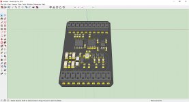
some 3D views:
Looking good JP.
The Don Audio inductors look like a good find.
I still think there is value in separating the output transformers from the filter boards so that different filters can be 'plugged in'?
Last edited:
Marcel/JP.
I still think there is value in separating the output transformers from the filter boards so that different filters can be 'plugged in'?
Attached are some pictures of the transformer output board for ppy's DSC2 decoder project (version 2.5.2). Very flexible and convenient - onboard output connectors, choice of transformers, choice of balanced or SE output, spaces for load components, etc - with gerber files available. I may just use this board 'as is' - thoughts?
Ray
Attachments

Hello Ray,
do you have ppy´s schematics, perhaps Chinese transformer datasheet? Do someone try Edcor ones?
The DSD-only filter board I´ve layouted is for JENSEN and Lundahl.
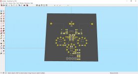
Attached DAC board (creepage constrains applied, WIMA and/or LCR polystyrene, high quality teflon PCB tube sockets), going on Beaglebone Black (with ppy´s reclocker) and COMBO384 using Marcel´s frontend.
JP
do you have ppy´s schematics, perhaps Chinese transformer datasheet? Do someone try Edcor ones?
The DSD-only filter board I´ve layouted is for JENSEN and Lundahl.
Attached DAC board (creepage constrains applied, WIMA and/or LCR polystyrene, high quality teflon PCB tube sockets), going on Beaglebone Black (with ppy´s reclocker) and COMBO384 using Marcel´s frontend.
JP
Attachments

do you have ppy´s schematics, perhaps Chinese transformer datasheet? Do someone try Edcor ones?
The DSD-only filter board I´ve layouted is for JENSEN and Lundahl.
Your DAC boards are looking good JP, very neat and compact. How many layers are you using?
All of ppy's files are available on his website but I'll PM you the files that might be useful.
I appreciate that your filter board is for Jensen and Lundahl transformers - I was being selfish with looking at ppy's output board as I'll definitely use the Lundahls.
I don't know if there is a datasheet for the Chinese transformers but if you think they might be a useful addition to the options I'm happy to try and track them down on taobao and see what information is available?
Regarding ppy's transformer output board, I think getting some of them fabricated is my fallback/default position unless you are willing to design separate filter and transformer boards that will plug together? Mono boards would be great as would having the output sockets on the transformer boards? I was going to design some boards myself but if you're willing to do it, and with your far superior skills/experience, there seems little point.
Ray
Here's a link to the Chinese transformers. They seem to be reasonably well regarded on the Signalyst thread.
R3 Jiayin 10K:10K permalloy audio transformer pre input cattle single end turn to balance signal isolation-in Transformers from Home Improvement on Aliexpress.com | Alibaba Group
Looking at the PCB for them;
R1 audio cattle isolation transformer 10K: 10K permalloy fever signal cattle-in Transformers from Home Improvement on Aliexpress.com | Alibaba Group
Suggests that they may be of similar spec to the Jensen JT-11P-HPC, though physically quite different.
Ray
Hello Marcel,
is it possible to split the CLKP/N and the CLK5P/N into dedicated righ/left differential pairs using other values for 27R0 and 33R0 resistors?
You´re right, only fanout clock drivers for +3.3V.
P.S.: DSD-only input fits COMBO 384; Beaglebone Bllack with ppy´s board not checked yet.
JP
is it possible to split the CLKP/N and the CLK5P/N into dedicated righ/left differential pairs using other values for 27R0 and 33R0 resistors?
You´re right, only fanout clock drivers for +3.3V.
P.S.: DSD-only input fits COMBO 384; Beaglebone Bllack with ppy´s board not checked yet.
JP
Attachments
...high quality teflon PCB tube sockets...
Which ones did you have in mind?
P.S.: DSD-only input fits COMBO 384; Beaglebone Bllack with ppy´s board not checked yet.
Hi JP. ppy's reclocker board is for the BBB only so an Amanero Combo 384 won't get the benefit of isolation/reclocking. Now, if your DSD-only input board included ppy's isolator/reclocker circuit then both BBB and Amanero would benefit - basically the same arrangement as on the front-end of ppy's Signalyst DSC board version 2.6
.jpg)
.jpg)
Hello Ray,
no decision at the moment (still braining) if:
- DSC 2.6: Beaglebone + Amenero + Marcel´s Frontend with ppy´s Reclocker
- one 20p connector for COMBO 384 (no reclocking) or Beagle Bone with ppy´s Reclocker
Could you ask please member @ppy if he should share chinese transformer drawings for CAD symbols definition?
JP
Hello Ray,
no decision at the moment (still braining) if:
- DSC 2.6: Beaglebone + Amenero + Marcel´s Frontend with ppy´s Reclocker
- one 20p connector for COMBO 384 (no reclocking) or Beagle Bone with ppy´s Reclocker
Could you ask please member @ppy if he should share chinese transformer drawings for CAD symbols definition?
JP
Thanks JP. I hope you don't mind me making suggestions? Reclocking incoming data is definitely beneficial.
I'll contact Pavel and see if he can help out.
Ray
is it possible to split the CLKP/N and the CLK5P/N into dedicated right/left differential pairs using other values for 27R0 and 33R0 resistors?
You could try laying them out as 80 ohm lines (I mean 80 ohm to ground, 160 ohm differential, so with a spacing between the lines of each pair that's large compared to the prepreg thickness) and give each line its own 56 ohm resistor at the source.
You´re right, only fanout clock drivers for +3.3V.
That's a pity. Understandable, because 5 V is getting rare, but still a pity.
Here's a link to the Chinese transformers. They seem to be reasonably well regarded on the Signalyst thread.
R3 Jiayin 10K:10K permalloy audio transformer pre input cattle single end turn to balance signal isolation-in Transformers from Home Improvement on Aliexpress.com | Alibaba Group
Looking at the PCB for them;
R1 audio cattle isolation transformer 10K: 10K permalloy fever signal cattle-in Transformers from Home Improvement on Aliexpress.com | Alibaba Group
Suggests that they may be of similar spec to the Jensen JT-11P-HPC, though physically quite different.
Ray
Based on the rather meager information Aliexpress provides about them, I would hook them up as in post #215 (that is, like the Lundahls), but without R3 and C9 (and of course with updated pinning).
no decision at the moment (still braining) if:
- DSC 2.6: Beaglebone + Amenero + Marcel´s Frontend with ppy´s Reclocker
- one 20p connector for COMBO 384 (no reclocking) or Beagle Bone with ppy´s Reclocker
One other thought on integrating ppy's reclocker with Marcel's front-end is that eliminates one 5V power supply, or at least removes the need for some wire hook-up, as the DAC and clean side of the reclocker could easily share the same supply.
I PM'ed Pavel about the Chinese transformer but no reply yet, though I understand he's wound down his audio activity because of work pressures.
Ray
Hello Ray, Marcel,
thank you Marcel for the proposal, I´ll see by routing carrier board.
Ray, I´m using BBB with Pavel´s redesigned reclocker (see attachment) as mezzanine on carrier board. It is a little bit tricky but the carrier boar also propose the option COMBO 384 with Pavel´s DSD26 reclocker.
So, its all for today.
JP
Attachments
Ray, I´m using BBB with Pavel´s redesigned reclocker (see attachment) as mezzanine on carrier board. It is a little bit tricky but the carrier boar also propose the option COMBO 384 with Pavel´s DSD26 reclocker.
Hi JP. I'm not sure I understand what you're proposing. I recognise the components of the isolator/reclocker and it obviously plugs into the board with Marcel's input stage - are you saying it will work with both the BBB and Amanero Combo384? Are they surface mounted header sockets I can see on the rendering of the board, so there are more below the board?
- Home
- Source & Line
- Digital Line Level
- Valve DAC from Linear Audio volume 13