Just waiting to hear back from Randy about whether he's in for a PCB, otherwise all ready to go with the order.
Ray
Ray
Last edited:
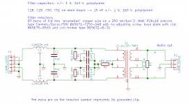
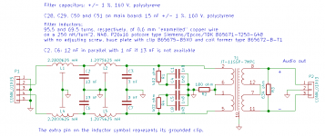
Attached are two suggested filter schematics with transformers for the raw-DSD version. I've drawn only one channel, the other is obviously the same.
The first is a third-order Butterworth at 42.9 kHz, the second a fifth-order Butterworth at 45 kHz. The first has a nicer-looking step response than the second, but worse suppression of out-of-band quantization noise. Out-of-band quantization noise may intermodulate in the amplifier and raise the in-band noise floor. Like I wrote this morning, I don't really know which one is most suitable.
Note that for the third-order filter, the termination impedance and the number of turns on the potcores are slightly different from what I wrote earlier.
Attachments
Thanks for preparing these filter schematics Marcel.
I guess experimentation will show which we prefer; the good thing is that a single PCB layout will support either design by omitting components (and adding wire links) as appropriate.
Ray
I don't really know which one is most suitable.
I guess experimentation will show which we prefer; the good thing is that a single PCB layout will support either design by omitting components (and adding wire links) as appropriate.
Ray
Indeed, and by lucky coincidence, both require 15 nF filter capacitors on the main board.
Yes, I saw that - lucky indeed!
By the way, you can change them into transformerless balanced versions (to drive a balanced input or a Broskie balanced to unbalanced converter) by replacing C1, C4, C5 and C8 with shorts, and removing everything to the right of C1, C4, C5 and C8.
The deed is done - I have just placed an order for PCBs for snax and my DSD-only Valve DAC projects.
Hello Marcel,
is something like a block diagram or wiring/interconnection diagram existing?
I´ve downloaded all documents/datas, going through this thread and will still have some questions.
I´m thinking that not the price is an issue but this build needs a lot of different skills.
Thank you for sharing1 Very appreciated. would be nice to see more interest so that a GB could be start with something that very different as usual candidate builds.
JP
Last edited:
Attached are two suggested filter schematics with transformers for the raw-DSD version. I've drawn only one channel, the other is obviously the same.
The first is a third-order Butterworth at 42.9 kHz, the second a fifth-order Butterworth at 45 kHz. The first has a nicer-looking step response than the second, but worse suppression of out-of-band quantization noise. Out-of-band quantization noise may intermodulate in the amplifier and raise the in-band noise floor. Like I wrote this morning, I don't really know which one is most suitable.
Note that for the third-order filter, the termination impedance and the number of turns on the potcores are slightly different from what I wrote earlier.
Could I ask why you choose 3rd & 5th order filters and why have different cutoff frequency?
is something like a block diagram or wiring/interconnection diagram existing?
The KiCad hierarchical schematics are pretty much what you're asking for?
Hello @nautibuoy
not really but I´m going through the schematics:
- one power supply generating -300VDC, -137VDC, -132VDC, 6.3VAC for heaters, +5VDC digital, muting I/O
- one 85A2 voltage reference (REF, powered with -300VDC, +5VDC and +3.3VDC) controlled by FPGA
- one reference (REF) oscillator generating CLK5P/M (powered with -300VDC, +5VDC and +3.3VDC)
- two, left and right FIRDAC: working on it
- the FPGA part: standby
- the output filters
IMHO, if constructive ideas are permitted, I would prefer one mainboard with power supplies and functional mezzanine PCB´s.
JP
Hello @nautibuoy
not really but I´m going through the schematics:
- one power supply generating -300VDC, -137VDC, -132VDC, 6.3VAC for heaters, +5VDC digital, muting I/O
- one 85A2 voltage reference (REF, powered with -300VDC, +5VDC and +3.3VDC) controlled by FPGA
- one reference (REF) oscillator generating CLK5P/M (powered with -300VDC, +5VDC and +3.3VDC)
- two, left and right FIRDAC: working on it
- the FPGA part: standby
- the output filters
IMHO, if constructive ideas are permitted, I would prefer one mainboard with power supplies and functional mezzanine PCB´s.
JP
Marcel has said he welcomes people working with his design.
It's a shame you didn't find the thread sooner as what you seem to be describing is where I proposed taking the PCB design a week or two back - unfortunately my lack of experience with KiCad was a bit of a risk so a couple of us are now in the process of obtaining PCBs using Marcel's PCB layout - I know you're rather better equipped to rework the PCB layout so I'll be watching with interest. We're going the DSD-only route so have dispensed with the FPGA section - we'll move the processing upstream using HQPlayer.
Ray
Hello Ray,
could you trace me (using Marcel´s schematics) the way you would wire the DAC as DSD-only DAC? Would be very appreciated.
JP
could you trace me (using Marcel´s schematics) the way you would wire the DAC as DSD-only DAC? Would be very appreciated.
JP
Hello Ray,
could you trace me (using Marcel´s schematics) the way you would wire the DAC as DSD-only DAC? Would be very appreciated.
JP
The starting point you need to think about is that the core of Marcel's DAC essentially required a DSD like data stream to work - it's a delta-sigma DAC, not multibit. That means that the FPGA section asyncronously converts multibit data to single-bit. Therefore, for the DSD version, you 'just' dispense with the FPGA and valve clock sections of Marcel's original DAC and feed the DAC cores with DSD data and clock signals from your source. It's obviously a little more complex than that and Marcel made various changes to suit but you'll find the detail in Marcel's DSD-only documentation attached to post #73
https://www.diyaudio.com/forums/dig...c-linear-audio-volume-13-a-8.html#post5847587
Subsequently, in post #84, Marcel made a full set of documentation and design files available and it is the gerber files from this that I've used to order PCBs for snax and myself.
Marcel was addressing different requirements with his original design in that he want to explore the technologies and to include things like spdif inputs. My personal preference is for the DSD-only version, either streaming native DSD data to it or, as I already do most of the time, convert PCM to DSD upstream using HQPlayer, resulting in a simpler (but still complex and challenging) project.
https://www.diyaudio.com/forums/dig...c-linear-audio-volume-13-a-9.html#post5856267
I hope that helps.
Ray
Last edited:
IMHO, if constructive ideas are permitted, I would prefer one mainboard with power supplies and functional mezzanine PCB´s.
JP
I just looked up the word mezzanine and am still not sure what you mean:
mezzanine noun - Definition, pictures, pronunciation and usage notes | Oxford Advanced Learner's Dictionary at OxfordLearnersDictionaries.com
mezzanine noun
BrE /ˈmezəniːn/
; NAmE /ˈmezəniːn/
1. a floor that is built between two floors of a building and is smaller than the other floors
2. (North American English) the first area of seats above the ground floor in a theatre; the first few rows of these seats
In any case, I prefer to have the FPGA section (or the data/clock input section for the DSD-only variant), the actual DACs, the clock generation and the voltage reference on one board to have maximum control over the wiring and the shielding. There is no need for the supply to be on the same board, but it saves a bunch of wires when it is put on the same board, especially when you take into account the mute circuitry.
Still, the complete database of the original version is available on the Linear Audio website (and the database of the DSD-only version on this site in this thread), so you can modify it and make any variant you would like to make.
I just looked up the word mezzanine and am still not sure what you mean:
My understanding is one mainboard with plug-in sub-boards for some sections of the design.
Hello Marcel,
is something like a block diagram or wiring/interconnection diagram existing?
There are several block diagrams in the article, but they may be too abstract. What level of detail and abstraction are you looking for?
I´ve downloaded all documents/datas, going through this thread and will still have some questions.
I'll be happy to answer them, if there are any that haven't been answered yet.
I´m thinking that not the price is an issue but this build needs a lot of different skills.
At the very least you need to be neither scared of -300 V supply voltages, nor of SMD soldering 😉
Could I ask why you choose 3rd & 5th order filters and why have different cutoff frequency?
The output signal of the E88CCs is a current, with low frequency components that represent the desired audio signal and with a lot of high-frequency quantization noise. To minimize crosstalk and/or voltage compliance issues, the high-frequency quantization noise should be shorted to ground. Hence, the filter has to start with a capacitor rather than a coil.
Not counting the DC blocking capacitors, the filter is essentially a C-L-C-L-... structure with a termination resistor at its end. As capacitors are much cheaper than the potcores, it is attractive to take an odd order: for example, going from fourth to fifth only requires extra capacitors, no extra potcores.
As far as I recall, the sigma-delta originally proposed by Sony for DSD64 has fifth-order noise shaping. Its quantization noise density goes up very fast just above 20 kHz, then changes into a fifth-order upward slope and eventually levels off. I don't remember exactly where it levels off, but it must be around 100 kHz or so.
A fifth-order Butterworth filter at 45 kHz will then just be sufficient to stop the density of the filtered noise from continuing to rise above 45 kHz. Instead, the filtered noise will level off around 45 kHz and start to drop above 100 kHz or so. Hence my choice for fifth order. (In the original valve DAC I even used a sixth order +/-0.05 degrees linear phase filter, but those have such a gradual roll-off that fifth-order Butterworth actually gives a better suppression of out-of-band quantization noise than sixth-order +/-0.05 degrees linear phase - and the phase response of a 45 kHz Butterworth filter is not bad at all up to 20 kHz.)
Still, most people on the noDAC thread seem to be satisfied with lower filter orders, and lower order filters do have a better transient response. Hence the third-order filter proposal. With this filter, the out-of-band quantization noise density will keep on rising gradually up to 100 kHz or whatever it may be and then drops.
The reason for the slightly different cut-off frequencies is related to rounding to E24 values - I just wanted something between 40 kHz and 50 kHz and tweaked the frequencies slightly until the values of the capacitors were as close as possible to E24 standard values.
Still, most people on the noDAC thread seem to be satisfied with lower filter orders, and lower order filters do have a better transient response. Hence the third-order filter proposal. With this filter, the out-of-band quantization noise density will keep on rising gradually up to 100 kHz or whatever it may be and then drops.
IMHO, no DAC project with Signalyst topology usually has 16 or 32 taps for analog FIR, where you can "digitally" attenuate out of band noise. In the case of 64OSR with 32taps, zero is multiples of 96kHz ( (24.576/8)/32=96kHz ), ie, 96kHz,192kHz,288kHz and more. Simple analog LPF(6db/oct) is enough to eliminate "getting away frequency" from analog FIR. SACD, which is now old technology without such "digital " filter in the analog domain, requires complicated filter design. If you have more than 16 taps, I don't think you need high order analog filter.
- Home
- Source & Line
- Digital Line Level
- Valve DAC from Linear Audio volume 13