You may want to adjust the capacitance as this:
https://tubedata.jp/sheets/082/e/EL12N.pdf
https://tubedata.jp/sheets/183/e/EL12spec.pdf
https://tubedata.jp/sheets/082/e/EL12N.pdf
https://tubedata.jp/sheets/183/e/EL12spec.pdf
Anyone have a working PC97 model or script?
I used one from the database and neither type of valve passes muster, get the same error code. Thanks in advance! 🙂

If it is an error in the model, I will start a new thread.
I used one from the database and neither type of valve passes muster, get the same error code. Thanks in advance! 🙂
If it is an error in the model, I will start a new thread.
https://www.diyaudio.com/community/threads/vacuum-tube-spice-models.243950/post-6989881
I seen many of errors are of similar nature.
Suppose you use this model library, and assume have saved this file in searchable dir/path and include with a directive ".inc pc97.inc"
U3 should be named as pc97.i3 not just pc97 as shown inside the model. If you're doubtful it pays to open the file and make sure..
Last edited:
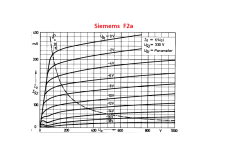

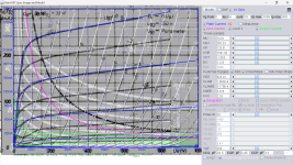
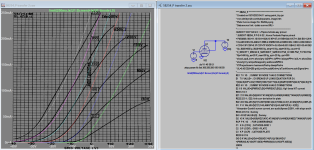
Here is F2A tetrode model:
Code:
**** F2A_P ******************************************
* Created on 03/30/2023 22:45 using paint_kip.jar
* www.dmitrynizh.com/tubeparams_image.htm
* Plate Curves image file: F2a-p.png
* Data source link: <plate curves URL>
*----------------------------------------------------------------------------------
.SUBCKT 2 P G2 G K ; LTSpice tetrode.asy pinout
* .SUBCKT F2A_P P G K G2 ; Koren Pentode Pspice pinout
+ PARAMS: MU=19.01 KG1=287.23 KP=133.51 KVB=1507.95 VCT=-1.053 EX=1.223 KG2=829.24 KNEE=3.318 KVC=2.19
+ KLAM=1.062E-9 KLAMG=3.173E-4 KNEE2=45.45 KNEX=9386.5  KNK=0.003457 KNG=0.003032 KNPL=7.6 KNSL=0.528 KNPR=212.54 KNSR=92.78
+ CCG=20.5P CGP=0.45P CCP=13P VGOFF=-0.6 IGA=0.001 IGB=0.3 IGC=8 IGEX=2
* Vp_MAX=1000 Ip_MAX=300 Vg_step=4 Vg_start=0 Vg_count=16
* X_MIN=59 Y_MIN=14 X_SIZE=807 Y_SIZE=606 FSZ_X=1296 FSZ_Y=736 XYGrid=true
* Rp=1400 Vg_ac=20 P_max=20 Vg_qui=-30 Vp_qui=300
* showLoadLine=n showIp=y isDHP=n isPP=n isAsymPP=n isUL=n showDissipLimit=y
* showIg1=y isInputSnapped=y addLocalNFB=n
* XYProjections=n harmonicPlot=y dissipPlot=n
* UL=0.43 EG2=250 gridLevel2=y addKink=y isTanhKnee=y advSigmoid=n
*----------------------------------------------------------------------------------
RE1  7 0  1G    ; DUMMY SO NODE 7 HAS 2 CONNECTIONS
E1   7 0  VALUE=  ; E1 BREAKS UP LONG EQUATION FOR G1.
+{V(G2,K)/KP*LOG(1+EXP((1/MU+(VCT+V(G,K))/SQRT(KVB+V(G2,K)*V(G2,K)))*KP))}
RE2  6 0  1G    ; DUMMY SO NODE 6 HAS 2 CONNECTIONS
E2  6 0  VALUE={(PWR(V(7),EX)+PWRS(V(7),EX))} ; Kg1 times KIT current
RE21 21 0 1
E21  21 0 VALUE={V(6)/KG1*ATAN((V(P,K)+KNEX)/KNEE)*TANH(V(P,K)/KNEE2)} ; Ip with knee but no slope and no kink
RE22 22 0 1 ; E22: kink curr deviation for plate
E22  22 0 VALUE={V(21)*LIMIT(KNK-V(G,K)*KNG,0,0.3)*(-ATAN((V(P,K)-KNPL)/KNSL)+ATAN((V(P,K)-KNPR)/KNSR))}
G1   P  K  VALUE={V(21)*(1+KLAMG*V(P,K))+KLAM*V(P,K) + V(22)}
* Alexander Gurskii screen current, see audioXpress 2/2011, with slope and kink added
RE43 43 K 1G ; Dummy
E43  43 G2 VALUE={0} ; Dummy
G2   43 K  VALUE={V(6)/KG2*(KVC-ATAN((V(P,K)+KNEX)/KNEE)*TANH(V(P,K)/KNEE2))/(1+KLAMG*V(P,K))-V(22)}
RCP  P K  1G     ; FOR CONVERGENCE
C1   K G  {CCG}  ; CATHODE-GRID 1
C2   G P  {CGP}  ; GRID 1-PLATE
C3   K P  {CCP}  ; CATHODE-PLATE
RE23 G 0 1G
GG G K VALUE={(IGA+IGB/(IGC+V(P,K)))*(MU/KG1)*
+(PWR(V(G,K)-VGOFF,IGEX)+PWRS(V(G,K)-VGOFF,IGEX))}
.ENDS
*$
Attachments
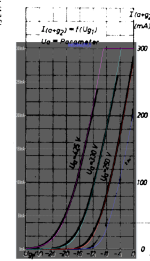
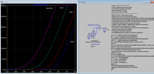

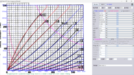
Have some issures with transfer curve for 5b/254 tetrode model, see attached, will see how later.
Here is 5B/254 triode model:
Here is 5B/254 triode model:
Code:
**** 5B254_T ** Advanced Grid Current **********************************
* Created on 03/31/2023 17:54 using paint_kit.jar 3.1
* www.dmitrynizh.com/tubeparams_image.htm
* Plate Curves image file: 5b254-t.png
* Data source link:
*----------------------------------------------------------------------------------
.SUBCKT TRIODE_5B254_T 1 2 3 ; Plate Grid Cathode
+ PARAMS: CCG=13P  CGP=0.1P CCP=7P
+ MU=11.15 KG1=496.68 KP=35.14 KVB=3034.83 VCT=-0.005625 EX=1.249
+ VGOFF=-0.6 IGA=0.001 IGB=0.3 IGC=8 IGEX=2
* Vp_MAX=350 Ip_MAX=300 Vg_step=5 Vg_start=15 Vg_count=11
* Rp=4000 Vg_ac=55 P_max=40 Vg_qui=-48 Vp_qui=300
* X_MIN=67 Y_MIN=25 X_SIZE=729 Y_SIZE=628 FSZ_X=1296 FSZ_Y=736 XYGrid=true
* showLoadLine=n showIp=y isDHT=n isPP=n isAsymPP=n showDissipLimit=y
* showIg1=y gridLevel2=y isInputSnapped=n
* XYProjections=n harmonicPlot=n dissipPlot=n
*----------------------------------------------------------------------------------
E1 7 0 VALUE={V(1,3)/KP*LOG(1+EXP(KP*(1/MU+(VCT+V(2,3))/SQRT(KVB+V(1,3)*V(1,3)))))}
RE1 7 0 1G  ; TO AVOID FLOATING NODES
G1 1 3 VALUE={(PWR(V(7),EX)+PWRS(V(7),EX))/KG1}
RCP 1 3 1G   ; TO AVOID FLOATING NODES
C1 2 3 {CCG} ; CATHODE-GRID
C2 2 1 {CGP} ; GRID=PLATE
C3 1 3 {CCP} ; CATHODE-PLATE
RE2 2 0 1G
EGC 8 0 VALUE={V(2,3)-VGOFF} ; POSITIVE GRID THRESHOLD
GG 2 3 VALUE={(IGA+IGB/(IGC+V(1,3)))*(MU/KG1)*(PWR(V(8),IGEX)+PWRS(V(8),IGEX))}
.ENDS
*$
Attachments
Here is F2A tetrode model:
Thank you very much, the model running very fine.
Attachments
Hi all
It's been several months since I have posted anything here.
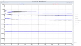
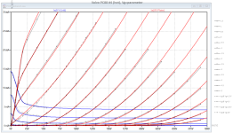
In the meantime, I created two new models, 6J4 and PC88. (PC93 and PC86 on half way)
Note that the 6J4 has quite a bit a hungry heater, while the PC88 suffers under significant sample tolerances ( the Philips a bit less than the Valvo types).
It's been several months since I have posted anything here.
In the meantime, I created two new models, 6J4 and PC88. (PC93 and PC86 on half way)
Note that the 6J4 has quite a bit a hungry heater, while the PC88 suffers under significant sample tolerances ( the Philips a bit less than the Valvo types).
Code:
*6J4 LTspice model based on the generic triode model from Adrian Immler, version i6
*A version log is at the end of this file
*100h BurnIn of 10 RCA tubes, sample selection and measurements done in January 2023
*Params fitted to the measured values by Adrian Immler, January 2023
*This model is accurate for Vg up to 1.5V.
*The high fit quality is presented at adrianimmler.simplesite.com
*History's best of tube describing art (plus some new ideas) is merged to this new approach.
*@ neg. Vg, Ia accuracy is similar to Koren models, and unrivaled for remote cutoff triodes
*@ small neg. Vg, the "Anlauf" current is considered.
*@ pos. Vg, Ig and Ia accuracy is on an unrivaled level (including neg. Va range!)
*This offers new simulation possibilities like grid resistor bias, backward plate modulated stages,
*Audion radio circuits, low voltage amps, guitar distortion stages or pulsed stages.
*It is assumed that there exists only 1 construction version of the 6J4, as this tube was not widely used.
*Hence, the two letters for the brand was skipped
*           i6 version is identical to the i5, but measurements done with HOT anode for highest accuracy
*           |  anode (plate)
*           |  | grid
*           |  | | cathode
*           |  | | |
.subckt 6J4.i6 A G K
+ params:
*Parameters for space charge current Is (100% assigned to Ia @ Vg < 0)
+ mu   = 46    ;Determines the voltage gain @ constant Ia
+ rad  = 3k2   ;Differential anode resistance, set @ Iad and Vg=0V
+ Vct  = 0.23  ;Offsets the Ia-traces on the Va axis. Electrode material's contact potential
+ kp   = 295   ;Mimics the island effect
+ xs   = 1.48  ;Determines the curve of the Ia traces. Typically between 1.2 and 1.8
+ kIsr = 45m   ;Va-indepedent part of the Is reduction when gridcurrent occurs
+ kvdg  = 150  ;Va-depedent part of the Is reduction when gridcurrent occurs
*
*Parameters for assigning the space charge current to Ia and Ig @ Vg > 0
+ kB   = 1.3   ;Describes how fast Ia drops to zero when Va approaches zero.
+ radl = 5     ;Differential resistance for the Ia emission limit @ very small Va and Vg > 0
+ tsh  = 12    ;Ia transmission sharpness from 1th to 2nd Ia area. Keep between 3 and 20. Start with 20.
+ xl   = 1.1   ;Exponent for the emission limit
*
*Parameters of the grid-cathode vacuum diode
+ kg = 560     ;Inverse scaling factor for the Va independent part of Ig (caution - interacts with xg!)
+ Vctg = -0.05 ;Offsets the log Ig-traces on the Vg axis. Electrode material's contact potential
+ xg   = 1.55  ;Determines the curve of the Ig slope versus (positive) Vg and Va >> 0
+ VT   = 0.16  ;Log(Ig) slope @ Vg<0. VT=k/q*Tk (cathodes absolute temp, typically 1150K)
+ rTr  = 0.6   ;ratio of VT for Igr. Typically 0.8
+ kVT  = 0     ;Va dependant koeff. of VT
+ gft1 = 0     ;reduces the steering voltage around Vg=-Vg0, for finetuning purposes
+ gft1a= 0.4   ;reduces the steering voltage around Vg=-Vg0. Effect decreases with 1/(1+kB*Va)
+ gft2 = 1     ;finetunes the Igr drop @ incrasing Va and around Vg=-Vg0
*
*Parameters for the caps
+ cag  = 4p    ;From TE datasheet
+ cak  = 0p24  ;From TE datasheet
+ cgk  = 5p5   ;From TE datasheet
*
*special purpose parameters
+ os = 1       ;Overall scaling factor, if a user wishes to simulate manufacturing tolerances
+ murc = 10    ;Mu of the remote cutoff triode
+ ksrc = 10G   ;Inverse Iarc gain factor for the remote cuttoff triode
+ kprc = 1k    ;Mimics the island effect for the remote cotoff triode
+ Vbatt = 0    ;heater battery voltage for direct heated battery triodes
+ Vdrmax = 100 ;max voltage of internal Vg drop, for convergence improvements
*
*Calculated parameters
+ Iad = {100/rad} ;Ia where the anode a.c. resistance is set according to rad.
+ ks = {pow(mu/(rad*xs*Iad**(1-1/xs)),-xs)} ;Reduces the unwished xs influence to the Ia slope
+ ksnom = {pow(mu/(rad*1.5*Iad**(1-1/1.5)),-1.5)} ;Sub-equation for calculating Vg0
+ Vg0 = {Vct + (Iad*ks)**(1/xs) - (Iad*ksnom)**(2/3)} ;Reduces the xs influence to Vct.
+ kl = {pow(1/(radl*xl*Ild**(1-1/xl)),-xl)} ;Reduces the xl influence to the Ia slope @ small Va
+ Ild = {sqrt(radl)*1m} ;Current where the Il a.c. resistance is set according to radl.
*
*Space charge current model
Rak A K 100G ;avoids "floating net" errors
Bft   ft 0 V=1/(1+pow(2*abs(v(G,Ki)+Vg0),3)) ;an auxiliary voltage to finetune the triode around Vg=-Vg0
Bggi GGi 0 V=(v(Gi,Ki)+Vg0)*(1/(1+kIsr*max(0, v(G,Ki)+Vg0))) - gft1*v(ft) - gft1a*v(ft)/(1+kB*v(Ahc)) ;Effective internal grid voltage.
Bahc Ahc 0 V=uramp(v(A,Ki)) ;Anode voltage, hard cut to zero @ neg. value
Bst   St 0 V=uramp(max(v(GGi)+v(A,Ki)/(mu), v(A,Ki)/kp*ln(1+exp(kp*(1/mu+v(GGi)/(1+v(Ahc)))))));Steering volt.
Bs    Ai Ki I=os/ks*pow(v(St),xs) ;Langmuir-Childs law for the space charge current Is
*Bstrc Strc 0 V=uramp(max(v(GGi)+v(Ahc)/(murc), v(Ahc)/kprc*ln(1+exp(kprc*(1/murc+v(GGi)/(1+v(Ahc)))))));FOR REMOTE CUTOFF TUBES ONLY
*Bsrc   Ai Ki I=os/ksrc*pow(v(Strc),xs) ;FOR REMOTE CUTOFF TUBES ONLY
*
*Anode current limit @ small Va
.func smin(z,y,k) {pow(pow(z+1f, -k)+pow(y+1f, -k), -1/k)} ;Min-function with smooth trans.
.func ssmin(z,y,k) {min(min(z,y), smin(z*1.003,y*1.003,k))};smin-function which suppresses small residual differencies
Ra  A Ai 1
Bgl Gi A I=uramp(i(Ra)-ssmin(1/kl*pow(v(Ahc),xl),i(Ra),tsh)) ;Ia emission limit
*
*Grid model
Rgk G K 10G ;avoids "floating net" errors
Bvdg G Gi I=1/kvdg*pow(v(G,Gi),1.5) ;Reduces the internal effective grid voltage when Ig rises
Bcoh G Gi I=pow(uramp(v(G,Gi)-Vdrmax),2) ;A convergence help which softly limits the internal Vg voltage drop.
Rgip G Gi 1G ;avoids some warnings
.func fVT() {VT*exp(-kVT*sqrt(v(A,Ki)))}
.func Ivd(Vvd, kvd, xvd, VTvd)  {if(Vvd < 3, 1/kvd*pow(VTvd*xvd*ln(1+exp(Vvd/VTvd/xvd)),xvd), 1/kvd*pow(Vvd, xvd))} ;Vacuum diode function
Bgvd G Ki I=Ivd(v(G,Ki) + Vctg + min(0,v(A,Ki)/mu), kg/os, xg, fVT()) ;limits the internal Vg for convergence reasons
Bstn Stn 0 V=v(GGi)+min(0,v(A,Ki))/mu ;special steering voltage, sensitive to negative Anodevoltages only
Bgr Gi Ai I= ivd(v(Stn),ks/os, xs, rTr*fVT())/(1+(kB+v(ft)*gft2)*v(Ahc));Is reflection to grid when Va approaches zero
*Bgr Gi Ai I=(ivd(v(Stn),ks/os, xs, rTr*fVT())+os/ksrc*pow(v(GGi),xs))/(1+(kB+v(ft)*gft2)*v(Ahc));FOR REMOTE CUTOFF TUBES ONLY
Bs0 Ai Ki  I=uramp(ivd(v(Stn),ks/os, xs, rTr*fVT()) - os/ks*pow(v(Stn),xs))
Bbatt Ki K V=Vbatt/2 ;for battery heated triodes; Offsets the average cathode potential to the half heater battery voltage
*
*Caps
C1 A G {cag}
C2 A K {cak}
C3 G K {cgk}
.ends
*
*Version log
*i1 :Initial version
*i2 :Pin order changed to the more common order A G K (Thanks to Markus Gyger for his tip)
*i3 :bugfix of the Ivd-function: now also usable for larger Vvd
*i4: Rgi replaced by a virtual vacuum diode (better convergence). ft1 deleted (no longer needed)
;2 new prarams for Ig finetuning @ Va and Vg near zero. New overall skaling factor os for aging etc.
*i5: improved convergence performance. PosVg/NegVa area now correct. Also accurate now for remote cutoff triodes!
*i6: identical to the i5, but tubes measured with hot anode (Pa=0.7*Pmax) for highest accuracy... and here the PC88 model.
BR Adrian
BR Adrian
Code:
*PC88 LTspice model based on the generic triode model from Adrian Immler, version i6
*A version log is at the end of this file
*100h BurnIn of 6 Philips and 8 Valvo tubes, sample selection and measurements done in January 2023
*Params fitted to the measured values by Adrian Immler, January 2023
*This model is accurate for Vg up to 1.5V.
*The fit quality is presented at adrianimmler.simplesite.com
*History's best of tube describing art (plus some new ideas) is merged to this new approach.
*@ neg. Vg, Ia accuracy is similar to Koren models, and unrivaled for remote cutoff triodes
*@ small neg. Vg, the "Anlauf" current is considered.
*@ pos. Vg, Ig and Ia accuracy is on an unrivaled level (including neg. Va range!)
*This offers new simulation possibilities like grid resistor bias, backward plate modulated stages,
*Audion radio circuits, low voltage amps, guitar distortion stages or pulsed stages.
*It is assumed that there exists only 1 construction version of the PC88, as Philips and Valvo used the same.
*Hence, the two letters for the brand was skipped. (Note that the Valvo showed larger sample tolerances!)
*            i6 version is identical to the i5, but measurements done with HOT anode for highest accuracy
*            |  anode (plate)
*            |  | grid
*            |  | | cathode
*            |  | | |
.subckt PC88.i6 A G K
+ params:
*Parameters for space charge current Is (100% assigned to Ia @ Vg < 0)
+ mu   = 73.5  ;Determines the voltage gain @ constant Ia
+ rad  = 3k6   ;Differential anode resistance, set @ Iad and Vg=0V
+ Vct  = 0.27  ;Offsets the Ia-traces on the Va axis. Electrode material's contact potential
+ kp   = 325   ;Mimics the island effect
+ xs   = 1.55  ;Determines the curve of the Ia traces. Typically between 1.2 and 1.8
+ kIsr = 0     ;Va-indepedent part of the Is reduction when gridcurrent occurs
+ kvdg  = 58   ;Va-depedent part of the Is reduction when gridcurrent occurs
*
*Parameters for assigning the space charge current to Ia and Ig @ Vg > 0
+ kB   = 0.4   ;Describes how fast Ia drops to zero when Va approaches zero.
+ radl = 600   ;Differential resistance for the Ia emission limit @ very small Va and Vg > 0
+ tsh  = 12    ;Ia transmission sharpness from 1th to 2nd Ia area. Keep between 3 and 20. Start with 20.
+ xl   = 1.3   ;Exponent for the emission limit
*
*Parameters of the grid-cathode vacuum diode
+ kg = 380     ;Inverse scaling factor for the Va independent part of Ig (caution - interacts with xg!)
+ Vctg = -0.2  ;Offsets the log Ig-traces on the Vg axis. Electrode material's contact potential
+ xg   = 1.6   ;Determines the curve of the Ig slope versus (positive) Vg and Va >> 0
+ VT   = 0.152 ;Log(Ig) slope @ Vg<0. VT=k/q*Tk (cathodes absolute temp, typically 1150K)
+ rTr  = 0.7   ;ratio of VT for Igr. Typically 0.8
+ kVT  = 0     ;Va dependant koeff. of VT
+ gft1 = 50m   ;reduces the steering voltage around Vg=-Vg0, for finetuning purposes
+ gft1a= 0.4   ;reduces the steering voltage around Vg=-Vg0. Effect decreases with 1/(1+kB*Va)
+ gft2 = 0.9   ;finetunes the Igr drop @ incrasing Va and around Vg=-Vg0
*
*Parameters for the caps
+ cag  = 1p2   ;From Philips datasheet
+ cak  = 0p055 ;From Philips datasheet
+ cgk  = 3p8   ;From Philips datasheet
*
*special purpose parameters
+ os = 1       ;Overall scaling factor, if a user wishes to simulate manufacturing tolerances
+ murc = 10    ;Mu of the remote cutoff triode
+ ksrc = 10G   ;Inverse Iarc gain factor for the remote cuttoff triode
+ kprc = 1k    ;Mimics the island effect for the remote cotoff triode
+ Vbatt = 0    ;heater battery voltage for direct heated battery triodes
+ Vdrmax = 100 ;max voltage of internal Vg drop, for convergence improvements
*
*Calculated parameters
+ Iad = {100/rad} ;Ia where the anode a.c. resistance is set according to rad.
+ ks = {pow(mu/(rad*xs*Iad**(1-1/xs)),-xs)} ;Reduces the unwished xs influence to the Ia slope
+ ksnom = {pow(mu/(rad*1.5*Iad**(1-1/1.5)),-1.5)} ;Sub-equation for calculating Vg0
+ Vg0 = {Vct + (Iad*ks)**(1/xs) - (Iad*ksnom)**(2/3)} ;Reduces the xs influence to Vct.
+ kl = {pow(1/(radl*xl*Ild**(1-1/xl)),-xl)} ;Reduces the xl influence to the Ia slope @ small Va
+ Ild = {sqrt(radl)*1m} ;Current where the Il a.c. resistance is set according to radl.
*
*Space charge current model
Rak A K 100G ;avoids "floating net" errors
Bft   ft 0 V=1/(1+pow(2*abs(v(G,Ki)+Vg0),3)) ;an auxiliary voltage to finetune the triode around Vg=-Vg0
Bggi GGi 0 V=(v(Gi,Ki)+Vg0)*(1/(1+kIsr*max(0, v(G,Ki)+Vg0))) - gft1*v(ft) - gft1a*v(ft)/(1+kB*v(Ahc)) ;Effective internal grid voltage.
Bahc Ahc 0 V=uramp(v(A,Ki)) ;Anode voltage, hard cut to zero @ neg. value
Bst   St 0 V=uramp(max(v(GGi)+v(A,Ki)/(mu), v(A,Ki)/kp*ln(1+exp(kp*(1/mu+v(GGi)/(1+v(Ahc)))))));Steering volt.
Bs    Ai Ki I=os/ks*pow(v(St),xs) ;Langmuir-Childs law for the space charge current Is
*Bstrc Strc 0 V=uramp(max(v(GGi)+v(Ahc)/(murc), v(Ahc)/kprc*ln(1+exp(kprc*(1/murc+v(GGi)/(1+v(Ahc)))))));FOR REMOTE CUTOFF TUBES ONLY
*Bsrc   Ai Ki I=os/ksrc*pow(v(Strc),xs) ;FOR REMOTE CUTOFF TUBES ONLY
*
*Anode current limit @ small Va
.func smin(z,y,k) {pow(pow(z+1f, -k)+pow(y+1f, -k), -1/k)} ;Min-function with smooth trans.
.func ssmin(z,y,k) {min(min(z,y), smin(z*1.003,y*1.003,k))};smin-function which suppresses small residual differencies
Ra  A Ai 1
Bgl Gi A I=uramp(i(Ra)-ssmin(1/kl*pow(v(Ahc),xl),i(Ra),tsh)) ;Ia emission limit
*
*Grid model
Rgk G K 10G ;avoids "floating net" errors
Bvdg G Gi I=1/kvdg*pow(v(G,Gi),1.5) ;Reduces the internal effective grid voltage when Ig rises
Bcoh G Gi I=pow(uramp(v(G,Gi)-Vdrmax),2) ;A convergence help which softly limits the internal Vg voltage drop.
Rgip G Gi 1G ;avoids some warnings
.func fVT() {VT*exp(-kVT*sqrt(v(A,Ki)))}
.func Ivd(Vvd, kvd, xvd, VTvd)  {if(Vvd < 3, 1/kvd*pow(VTvd*xvd*ln(1+exp(Vvd/VTvd/xvd)),xvd), 1/kvd*pow(Vvd, xvd))} ;Vacuum diode function
Bgvd G Ki I=Ivd(v(G,Ki) + Vctg + min(0,v(A,Ki)/mu), kg/os, xg, fVT()) ;limits the internal Vg for convergence reasons
Bstn Stn 0 V=v(GGi)+min(0,v(A,Ki))/mu ;special steering voltage, sensitive to negative Anodevoltages only
Bgr Gi Ai I= ivd(v(Stn),ks/os, xs, rTr*fVT())/(1+(kB+v(ft)*gft2)*v(Ahc));Is reflection to grid when Va approaches zero
*Bgr Gi Ai I=(ivd(v(Stn),ks/os, xs, rTr*fVT())+os/ksrc*pow(v(GGi),xs))/(1+(kB+v(ft)*gft2)*v(Ahc));FOR REMOTE CUTOFF TUBES ONLY
Bs0 Ai Ki  I=uramp(ivd(v(Stn),ks/os, xs, rTr*fVT()) - os/ks*pow(v(Stn),xs))
Bbatt Ki K V=Vbatt/2 ;for battery heated triodes; Offsets the average cathode potential to the half heater battery voltage
*
*Caps
C1 A G {cag}
C2 A K {cak}
C3 G K {cgk}
.ends
*
*Version log
*i1 :Initial version
*i2 :Pin order changed to the more common order A G K (Thanks to Markus Gyger for his tip)
*i3 :bugfix of the Ivd-function: now also usable for larger Vvd
*i4: Rgi replaced by a virtual vacuum diode (better convergence). ft1 deleted (no longer needed)
;2 new prarams for Ig finetuning @ Va and Vg near zero. New overall skaling factor os for aging etc.
*i5: improved convergence performance. PosVg/NegVa area now correct. Also accurate now for remote cutoff triodes!
*i6: identical to the i5, but tubes measured with hot anode (Pa=0.7*Pmax) for highest accuracy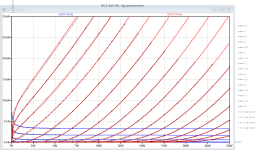
Hi all
A further model of mine...
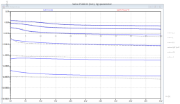
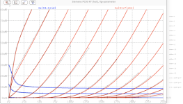
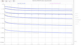
This time the PC93. Note that this tube, while keeping its heater power moderate, provides an exceptional low plate resistance of less than 2kOhm!
BR Adrian
A further model of mine...
This time the PC93. Note that this tube, while keeping its heater power moderate, provides an exceptional low plate resistance of less than 2kOhm!
BR Adrian
Code:
*PC93 LTspice model based on the generic triode model from Adrian Immler, version i6
*A version log is at the end of this file
*100h BurnIn of 10 Siemens tubes, sample selection and measurements done in April 2023
*Params fitted to the measured values by Adrian Immler, April 2023
*This model is accurate for Vg up to 4V.
*The fit quality is presented at adrianimmler.simplesite.com
*History's best of tube describing art (plus some new ideas) is merged to this new approach.
*@ neg. Vg, Ia accuracy is similar to Koren models, and unrivaled for remote cutoff triodes
*@ small neg. Vg, the "Anlauf" current is considered.
*@ pos. Vg, Ig and Ia accuracy is on an unrivaled level (including neg. Va range!)
*This offers new simulation possibilities like grid resistor bias, backward plate modulated stages,
*Audion radio circuits, low voltage amps, guitar distortion stages or pulsed stages.
*It is assumed that there exists only 1 construction version of the PC93
*Hence, the two letters for the brand was skipped.
*            i6 version is identical to the i5, but measurements done with HOT anode for highest accuracy
*            |  anode (plate)
*            |  | grid
*            |  | | cathode
*            |  | | |
.subckt PC93.i6 A G K
+ params:
*Parameters for space charge current Is (100% assigned to Ia @ Vg < 0)
+ mu   = 16.7  ;Determines the voltage gain @ constant Ia
+ rad  = 780   ;Differential anode resistance, set @ Iad and Vg=0V
+ Vct  = 0.8   ;Offsets the Ia-traces on the Va axis. Electrode material's contact potential
+ kp   = 77    ;Mimics the island effect
+ xs   = 1.4   ;Determines the curve of the Ia traces. Typically between 1.2 and 1.8
+ kIsr = 0     ;Va-indepedent part of the Is reduction when gridcurrent occurs
+ kvdg  = 115  ;Va-depedent part of the Is reduction when gridcurrent occurs
*
*Parameters for assigning the space charge current to Ia and Ig @ Vg > 0
+ kB   = 0.6   ;Describes how fast Ia drops to zero when Va approaches zero.
+ radl = 220   ;Differential resistance for the Ia emission limit @ very small Va and Vg > 0
+ tsh  = 6     ;Ia transmission sharpness from 1th to 2nd Ia area. Keep between 3 and 20. Start with 20.
+ xl   = 1.3   ;Exponent for the emission limit
*
*Parameters of the grid-cathode vacuum diode
+ kg = 550     ;Inverse scaling factor for the Va independent part of Ig (caution - interacts with xg!)
+ Vctg = -0.1  ;Offsets the log Ig-traces on the Vg axis. Electrode material's contact potential
+ xg   = 1.1   ;Determines the curve of the Ig slope versus (positive) Vg and Va >> 0
+ VT   = 0.168 ;Log(Ig) slope @ Vg<0. VT=k/q*Tk (cathodes absolute temp, typically 1150K)
+ rTr  = 0.6   ;ratio of VT for Igr. Typically 0.8
+ kVT  = 25m   ;Va dependant koeff. of VT
+ gft1 = 0     ;reduces the steering voltage around Vg=-Vg0, for finetuning purposes
+ gft1a= 0     ;reduces the steering voltage around Vg=-Vg0. Effect decreases with 1/(1+kB*Va)
+ gft2 = 0.3   ;finetunes the Igr drop @ incrasing Va and around Vg=-Vg0
*
*Parameters for the caps
+ cag  = 1p75  ;From "Röhren Halbleiter Bauteile Taschenbuch 1963"
+ cak  = 0p22  ;From "Röhren Halbleiter Bauteile Taschenbuch 1963"
+ cgk  = 2p2   ;From "Röhren Halbleiter Bauteile Taschenbuch 1963"
*
*special purpose parameters
+ os = 1       ;Overall scaling factor, if a user wishes to simulate manufacturing tolerances
+ murc = 10    ;Mu of the remote cutoff triode
+ ksrc = 10G   ;Inverse Iarc gain factor for the remote cuttoff triode
+ kprc = 1k    ;Mimics the island effect for the remote cotoff triode
+ Vbatt = 0    ;heater battery voltage for direct heated battery triodes
+ Vdrmax = 100 ;max voltage of internal Vg drop, for convergence improvements
*
*Calculated parameters
+ Iad = {100/rad} ;Ia where the anode a.c. resistance is set according to rad.
+ ks = {pow(mu/(rad*xs*Iad**(1-1/xs)),-xs)} ;Reduces the unwished xs influence to the Ia slope
+ ksnom = {pow(mu/(rad*1.5*Iad**(1-1/1.5)),-1.5)} ;Sub-equation for calculating Vg0
+ Vg0 = {Vct + (Iad*ks)**(1/xs) - (Iad*ksnom)**(2/3)} ;Reduces the xs influence to Vct.
+ kl = {pow(1/(radl*xl*Ild**(1-1/xl)),-xl)} ;Reduces the xl influence to the Ia slope @ small Va
+ Ild = {sqrt(radl)*1m} ;Current where the Il a.c. resistance is set according to radl.
*
*Space charge current model
Rak A K 100G ;avoids "floating net" errors
Bft   ft 0 V=1/(1+pow(2*abs(v(G,Ki)+Vg0),3)) ;an auxiliary voltage to finetune the triode around Vg=-Vg0
Bggi GGi 0 V=(v(Gi,Ki)+Vg0)*(1/(1+kIsr*max(0, v(G,Ki)+Vg0))) - gft1*v(ft) - gft1a*v(ft)/(1+kB*v(Ahc)) ;Effective internal grid voltage.
Bahc Ahc 0 V=uramp(v(A,Ki)) ;Anode voltage, hard cut to zero @ neg. value
Bst   St 0 V=uramp(max(v(GGi)+v(A,Ki)/(mu), v(A,Ki)/kp*ln(1+exp(kp*(1/mu+v(GGi)/(1+v(Ahc)))))));Steering volt.
Bs    Ai Ki I=os/ks*pow(v(St),xs) ;Langmuir-Childs law for the space charge current Is
*Bstrc Strc 0 V=uramp(max(v(GGi)+v(Ahc)/(murc), v(Ahc)/kprc*ln(1+exp(kprc*(1/murc+v(GGi)/(1+v(Ahc)))))));FOR REMOTE CUTOFF TUBES ONLY
*Bsrc   Ai Ki I=os/ksrc*pow(v(Strc),xs) ;FOR REMOTE CUTOFF TUBES ONLY
*
*Anode current limit @ small Va
.func smin(z,y,k) {pow(pow(z+1f, -k)+pow(y+1f, -k), -1/k)} ;Min-function with smooth trans.
.func ssmin(z,y,k) {min(min(z,y), smin(z*1.003,y*1.003,k))};smin-function which suppresses small residual differencies
Ra  A Ai 1
Bgl Gi A I=uramp(i(Ra)-ssmin(1/kl*pow(v(Ahc),xl),i(Ra),tsh)) ;Ia emission limit
*
*Grid model
Rgk G K 10G ;avoids "floating net" errors
Bvdg G Gi I=1/kvdg*pow(v(G,Gi),1.5) ;Reduces the internal effective grid voltage when Ig rises
Bcoh G Gi I=pow(uramp(v(G,Gi)-Vdrmax),2) ;A convergence help which softly limits the internal Vg voltage drop.
Rgip G Gi 1G ;avoids some warnings
.func fVT() {VT*exp(-kVT*sqrt(v(A,Ki)))}
.func Ivd(Vvd, kvd, xvd, VTvd)  {if(Vvd < 3, 1/kvd*pow(VTvd*xvd*ln(1+exp(Vvd/VTvd/xvd)),xvd), 1/kvd*pow(Vvd, xvd))} ;Vacuum diode function
Bgvd G Ki I=Ivd(v(G,Ki) + Vctg + min(0,v(A,Ki)/mu), kg/os, xg, fVT()) ;limits the internal Vg for convergence reasons
Bstn Stn 0 V=v(GGi)+min(0,v(A,Ki))/mu ;special steering voltage, sensitive to negative Anodevoltages only
Bgr Gi Ai I= ivd(v(Stn),ks/os, xs, rTr*fVT())/(1+(kB+v(ft)*gft2)*v(Ahc));Is reflection to grid when Va approaches zero
*Bgr Gi Ai I=(ivd(v(Stn),ks/os, xs, rTr*fVT())+os/ksrc*pow(v(GGi),xs))/(1+(kB+v(ft)*gft2)*v(Ahc));FOR REMOTE CUTOFF TUBES ONLY
Bs0 Ai Ki  I=uramp(ivd(v(Stn),ks/os, xs, rTr*fVT()) - os/ks*pow(v(Stn),xs))
Bbatt Ki K V=Vbatt/2 ;for battery heated triodes; Offsets the average cathode potential to the half heater battery voltage
*
*Caps
C1 A G {cag}
C2 A K {cak}
C3 G K {cgk}
.ends
*
*Version log
*i1 :Initial version
*i2 :Pin order changed to the more common order A G K (Thanks to Markus Gyger for his tip)
*i3 :bugfix of the Ivd-function: now also usable for larger Vvd
*i4: Rgi replaced by a virtual vacuum diode (better convergence). ft1 deleted (no longer needed)
;2 new prarams for Ig finetuning @ Va and Vg near zero. New overall skaling factor os for aging etc.
*i5: improved convergence performance. PosVg/NegVa area now correct. Also accurate now for remote cutoff triodes!
*i6: identical to the i5, but tubes measured with hot anode (Pa=0.7*Pmax) for highest accuracy
Attachments
Hi all... and here the PC88 model.
BR Adrian
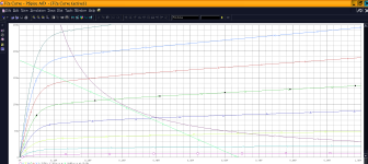
This hour, I recognized convergence issues of my PC88 model I provided some days ago, when the model is used in dc-coupled stages.
This is because I forgot to tune a parameter - this is now done!
So, here the new, more stable PC88 model:
Code:
*PC88 LTspice model based on the generic triode model from Adrian Immler, version i6
*A version log is at the end of this file
*100h BurnIn of 6 Philips and 8 Valvo tubes, sample selection and measurements done in January 2023
*Params fitted to the measured values by Adrian Immler, January 2023
*This model is accurate for Vg up to 1.5V.
*The fit quality is presented at adrianimmler.simplesite.com
*History's best of tube describing art (plus some new ideas) is merged to this new approach.
*@ neg. Vg, Ia accuracy is similar to Koren models, and unrivaled for remote cutoff triodes
*@ small neg. Vg, the "Anlauf" current is considered.
*@ pos. Vg, Ig and Ia accuracy is on an unrivaled level (including neg. Va range!)
*This offers new simulation possibilities like grid resistor bias, backward plate modulated stages,
*Audion radio circuits, low voltage amps, guitar distortion stages or pulsed stages.
*It is assumed that there exists only 1 construction version of the PC88, as Philips and Valvo used the same.
*Hence, the two letters for the brand was skipped. (Note that the Valvo showed larger sample tolerances!)
*            i6 version is identical to the i5, but measurements done with HOT anode for highest accuracy
*            |  anode (plate)
*            |  | grid
*            |  | | cathode
*            |  | | |
.subckt PC88.i6 A G K
+ params:
*Parameters for space charge current Is (100% assigned to Ia @ Vg < 0)
+ mu   = 73.5  ;Determines the voltage gain @ constant Ia
+ rad  = 3k6   ;Differential anode resistance, set @ Iad and Vg=0V
+ Vct  = 0.27  ;Offsets the Ia-traces on the Va axis. Electrode material's contact potential
+ kp   = 325   ;Mimics the island effect
+ xs   = 1.55  ;Determines the curve of the Ia traces. Typically between 1.2 and 1.8
+ kIsr = 0     ;Va-indepedent part of the Is reduction when gridcurrent occurs
+ kvdg  = 58   ;Va-depedent part of the Is reduction when gridcurrent occurs
*
*Parameters for assigning the space charge current to Ia and Ig @ Vg > 0
+ kB   = 0.4   ;Describes how fast Ia drops to zero when Va approaches zero.
+ radl = 600   ;Differential resistance for the Ia emission limit @ very small Va and Vg > 0
+ tsh  = 12    ;Ia transmission sharpness from 1th to 2nd Ia area. Keep between 3 and 20. Start with 20.
+ xl   = 1.3   ;Exponent for the emission limit
*
*Parameters of the grid-cathode vacuum diode
+ kg = 380     ;Inverse scaling factor for the Va independent part of Ig (caution - interacts with xg!)
+ Vctg = -0.2  ;Offsets the log Ig-traces on the Vg axis. Electrode material's contact potential
+ xg   = 1.6   ;Determines the curve of the Ig slope versus (positive) Vg and Va >> 0
+ VT   = 0.152 ;Log(Ig) slope @ Vg<0. VT=k/q*Tk (cathodes absolute temp, typically 1150K)
+ rTr  = 0.7   ;ratio of VT for Igr. Typically 0.8
+ kVT  = 0     ;Va dependant koeff. of VT
+ gft1 = 50m   ;reduces the steering voltage around Vg=-Vg0, for finetuning purposes
+ gft1a= 0.4   ;reduces the steering voltage around Vg=-Vg0. Effect decreases with 1/(1+kB*Va)
+ gft2 = 0.9   ;finetunes the Igr drop @ incrasing Va and around Vg=-Vg0
*
*Parameters for the caps
+ cag  = 1p2   ;From TE datasheet
+ cak  = 0p055 ;From TE datasheet
+ cgk  = 3p8   ;From TE datasheet
*
*special purpose parameters
+ os = 1       ;Overall scaling factor, if a user wishes to simulate manufacturing tolerances
+ murc = 10    ;Mu of the remote cutoff triode
+ ksrc = 10G   ;Inverse Iarc gain factor for the remote cuttoff triode
+ kprc = 1k    ;Mimics the island effect for the remote cotoff triode
+ Vbatt = 0    ;heater battery voltage for direct heated battery triodes
+ Vdrmax = 0.75;max voltage of internal Vg drop, for convergence improvements
*
*Calculated parameters
+ Iad = {100/rad} ;Ia where the anode a.c. resistance is set according to rad.
+ ks = {pow(mu/(rad*xs*Iad**(1-1/xs)),-xs)} ;Reduces the unwished xs influence to the Ia slope
+ ksnom = {pow(mu/(rad*1.5*Iad**(1-1/1.5)),-1.5)} ;Sub-equation for calculating Vg0
+ Vg0 = {Vct + (Iad*ks)**(1/xs) - (Iad*ksnom)**(2/3)} ;Reduces the xs influence to Vct.
+ kl = {pow(1/(radl*xl*Ild**(1-1/xl)),-xl)} ;Reduces the xl influence to the Ia slope @ small Va
+ Ild = {sqrt(radl)*1m} ;Current where the Il a.c. resistance is set according to radl.
*
*Space charge current model
Rak A K 100G ;avoids "floating net" errors
Bft   ft 0 V=1/(1+pow(2*abs(v(G,Ki)+Vg0),3)) ;an auxiliary voltage to finetune the triode around Vg=-Vg0
Bggi GGi 0 V=(v(Gi,Ki)+Vg0)*(1/(1+kIsr*max(0, v(G,Ki)+Vg0))) - gft1*v(ft) - gft1a*v(ft)/(1+kB*v(Ahc)) ;Effective internal grid voltage.
Bahc Ahc 0 V=uramp(v(A,Ki)) ;Anode voltage, hard cut to zero @ neg. value
Bst   St 0 V=uramp(max(v(GGi)+v(A,Ki)/(mu), v(A,Ki)/kp*ln(1+exp(kp*(1/mu+v(GGi)/(1+v(Ahc)))))));Steering volt.
Bs    Ai Ki I=os/ks*pow(v(St),xs) ;Langmuir-Childs law for the space charge current Is
*Bstrc Strc 0 V=uramp(max(v(GGi)+v(Ahc)/(murc), v(Ahc)/kprc*ln(1+exp(kprc*(1/murc+v(GGi)/(1+v(Ahc)))))));FOR REMOTE CUTOFF TUBES ONLY
*Bsrc   Ai Ki I=os/ksrc*pow(v(Strc),xs) ;FOR REMOTE CUTOFF TUBES ONLY
*
*Anode current limit @ small Va
.func smin(z,y,k) {pow(pow(z+1f, -k)+pow(y+1f, -k), -1/k)} ;Min-function with smooth trans.
.func ssmin(z,y,k) {min(min(z,y), smin(z*1.003,y*1.003,k))};smin-function which suppresses small residual differencies
Ra  A Ai 1
Bgl Gi A I=uramp(i(Ra)-ssmin(1/kl*pow(v(Ahc),xl),i(Ra),tsh)) ;Ia emission limit
*
*Grid model
Rgk G K 10G ;avoids "floating net" errors
Bvdg G Gi I=1/kvdg*pow(v(G,Gi),1.5) ;Reduces the internal effective grid voltage when Ig rises
Bcoh G Gi I=pow(uramp(v(G,Gi)-Vdrmax),2) ;A convergence help which softly limits the internal Vg voltage drop.
Rgip G Gi 1G ;avoids some warnings
.func fVT() {VT*exp(-kVT*sqrt(v(A,Ki)))}
.func Ivd(Vvd, kvd, xvd, VTvd)  {if(Vvd < 3, 1/kvd*pow(VTvd*xvd*ln(1+exp(Vvd/VTvd/xvd)),xvd), 1/kvd*pow(Vvd, xvd))} ;Vacuum diode function
Bgvd G Ki I=Ivd(v(G,Ki) + Vctg + min(0,v(A,Ki)/mu), kg/os, xg, fVT()) ;limits the internal Vg for convergence reasons
Bstn Stn 0 V=v(GGi)+min(0,v(A,Ki))/mu ;special steering voltage, sensitive to negative Anodevoltages only
Bgr Gi Ai I= ivd(v(Stn),ks/os, xs, rTr*fVT())/(1+(kB+v(ft)*gft2)*v(Ahc));Is reflection to grid when Va approaches zero
*Bgr Gi Ai I=(ivd(v(Stn),ks/os, xs, rTr*fVT())+os/ksrc*pow(v(GGi),xs))/(1+(kB+v(ft)*gft2)*v(Ahc));FOR REMOTE CUTOFF TUBES ONLY
Bs0 Ai Ki  I=uramp(ivd(v(Stn),ks/os, xs, rTr*fVT()) - os/ks*pow(v(Stn),xs))
Bbatt Ki K V=Vbatt/2 ;for battery heated triodes; Offsets the average cathode potential to the half heater battery voltage
*
*Caps
C1 A G {cag}
C2 A K {cak}
C3 G K {cgk}
.ends
*
*Version log
*i1 :Initial version
*i2 :Pin order changed to the more common order A G K (Thanks to Markus Gyger for his tip)
*i3 :bugfix of the Ivd-function: now also usable for larger Vvd
*i4: Rgi replaced by a virtual vacuum diode (better convergence). ft1 deleted (no longer needed)
;2 new prarams for Ig finetuning @ Va and Vg near zero. New overall skaling factor os for aging etc.
*i5: improved convergence performance. PosVg/NegVa area now correct. Also accurate now for remote cutoff triodes!
*i6: identical to the i5, but tubes measured with hot anode (Pa=0.7*Pmax) for highest accuracy
I apologize for this mistake.
BR Adrian
PS: I have also to check the 6J4 model. I will do this tomorrow.
Thank you once again for the models Adrian.
Is PC93 anything like 3AF4A?
BTW, I found out that PC97 does have a US equivalent, 4FY5.
Is PC93 anything like 3AF4A?
BTW, I found out that PC97 does have a US equivalent, 4FY5.
Hi Rongon
The PC93 is a different construction (not equivalent to the 3AF4A). Both have more or less the same mu, but the PC93 has a 20% larger gm.
Thanks for the hint regarding the PC97 equivalent!
The PC93 is a different construction (not equivalent to the 3AF4A). Both have more or less the same mu, but the PC93 has a 20% larger gm.
Thanks for the hint regarding the PC97 equivalent!
(...)
PS: I have also to check the 6J4 model. I will do this tomorrow.
I checked in the meantime - all is fine the 6J4!
Anyone have a working PC97 model or script?
I used one from the database and neither type of valve passes muster, get the same error code. Thanks in advance! 🙂
If it is an error in the model, I will start a new thread.
I use Adrian Immler's PC97 model.
https://www.diyaudio.com/community/threads/vacuum-tube-spice-models.243950/page-147#post-6631104
Is that what you're using when you see that error?
Although not strictly a tube, it can be used as a tube replacement.
Does someone has a better model measured from actual loadlines from a LND150 ?
The default one from the supertex.lib doesn't seem to be very accurate unfortunately.
Does someone has a better model measured from actual loadlines from a LND150 ?
The default one from the supertex.lib doesn't seem to be very accurate unfortunately.
I have three in my standard.mos file:
I don't know if they're accurate at all. I haven't used LND150 in anything yet. Hopefully one of these is an improvement.
Code:
.MODEL LND150 NMOS (LEVEL=3 RS=150.00 NSUB=5.0E13 DELTA=0.1 KAPPA=1.O TPG=1 CGDO=2.1716E-12 RD=40.0 VTO=-2.0 VMAX=1.0E8 ETA=0.1 NFS=6.6E10 TOX=1.0E-7 LD=1.698E-9 UO=862.425 XJ=6.4666E-7 THETA=1.0E-5 CGSO=5.09E-10 L=10.0E-6 W=600E-6)

.model LND150_ VDMOS (Rg=100 Vto={-1.4-(5m-1m)*(Temp-25)} Lambda=2m Rs={70*(1+2.6m*(Temp-25))} Kp={3m*((Temp+273)/(273+25))**-(2-1.5)} Ksubthres={0.095*(1+3m*(Temp-25))} Mtriode=0.6 Rd={300*(1+3m*(Temp-25))} Cgdmax=5p Cgdmin=3p a=0.3 Cgs=3p Cjo=15p m=0.7 VJ=0.75 IS=15p N=1.5 EG=1.1 Rb=100 Vds=400 Ron=600 mfg=IH1911)

.MODEL LND250 NMOS (LEVEL=3 RS=150.00 NSUB=5.0E13 KAPPA=1 TPG=1 CGDO=2.1716E-12 RD=40 VTO=-2.0 VMAX=1.0E8 ETA=0.1 NFS=6.6E10 TOX=1.0E-7 LD=1.698E-9 UO=862.425 XJ=6.4666E-7 THETA=1.0E-5 CGSO=5.09E-10 L=10.0E-6 W=600E-6)
I don't know if they're accurate at all. I haven't used LND150 in anything yet. Hopefully one of these is an improvement.
- Home
- Amplifiers
- Tubes / Valves
- Vacuum Tube SPICE Models