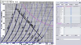
Type 50 RCA model:
DHT model:
Code:
**** 50 ** Advanced Grid Current **********************************
* Created on 09/20/2021 10:04 using paint_kit.jar 3.1
* [url=http://www.dmitrynizh.com/tubeparams_image.htm]Model Paint Tools: Trace Tube Parameters over Plate Curves, Interactively[/url]
* Plate Curves image file: 50.png
* Data source link:
*----------------------------------------------------------------------------------
.SUBCKT 50 1 2 3 ; Plate Grid Cathode
+ PARAMS: CCG=4.2P  CGP=7.1P CCP=3.4P
+ MU=3.832 KG1=4456.66 KP=38.05 KVB=3355.76 VCT=-0.18 EX=1.324
+ VGOFF=-0.6 IGA=0.001 IGB=0.3 IGC=8 IGEX=1.64
* Vp_MAX=800 Ip_MAX=120 Vg_step=20 Vg_start=0 Vg_count=9
* Rp=4000 Vg_ac=55 P_max=40 Vg_qui=-48 Vp_qui=300
* X_MIN=10 Y_MIN=40 X_SIZE=830 Y_SIZE=619 FSZ_X=1296 FSZ_Y=736 XYGrid=true
* showLoadLine=n showIp=y isDHT=n isPP=n isAsymPP=n showDissipLimit=y
* showIg1=y gridLevel2=y isInputSnapped=n
* XYProjections=n harmonicPlot=n dissipPlot=n
*----------------------------------------------------------------------------------
E1 7 0 VALUE={V(1,3)/KP*LOG(1+EXP(KP*(1/MU+(VCT+V(2,3))/SQRT(KVB+V(1,3)*V(1,3)))))}
RE1 7 0 1G  ; TO AVOID FLOATING NODES
G1 1 3 VALUE={(PWR(V(7),EX)+PWRS(V(7),EX))/KG1}
RCP 1 3 1G   ; TO AVOID FLOATING NODES
C1 2 3 {CCG} ; CATHODE-GRID
C2 2 1 {CGP} ; GRID=PLATE
C3 1 3 {CCP} ; CATHODE-PLATE
RE2 2 0 1G
EGC 8 0 VALUE={V(2,3)-VGOFF} ; POSITIVE GRID THRESHOLD
GG 2 3 VALUE={(IGA+IGB/(IGC+V(1,3)))*(MU/KG1)*(PWR(V(8),IGEX)+PWRS(V(8),IGEX))}
.ENDS
*$
DHT model:
Code:
**** 50 ** Composite DHT with Advanced Grid Current **************
* Created on 09/20/2021 10:06 using paint_kit.jar 3.1
* [url=http://www.dmitrynizh.com/tubeparams_image.htm]Model Paint Tools: Trace Tube Parameters over Plate Curves, Interactively[/url]
* Plate Curves image file: 50.png
* Data source link:
*----------------------------------------------------------------------------------
.SUBCKT DHT_50_A2 1 2 3 4 ; P G K1 K2
+ PARAMS: CCG=4.2P  CGP=7.1P CCP=3.4P RFIL=6
+ MU=3.832 KG1=4456.66 KP=38.05 KVB=3355.76 VCT=-0.18 EX=1.324
+ VGOFF=-0.6 IGA=0.001 IGB=0.3 IGC=8 IGEX=1.64
* Vp_MAX=800 Ip_MAX=120 Vg_step=20 Vg_start=0 Vg_count=9
* Rp=4000 Vg_ac=55 P_max=40 Vg_qui=-48 Vp_qui=300
* X_MIN=10 Y_MIN=40 X_SIZE=830 Y_SIZE=619 FSZ_X=1296 FSZ_Y=736 XYGrid=true
* showLoadLine=n showIp=y isDHT=y isPP=n isAsymPP=n showDissipLimit=y
* showIg1=y gridLevel2=y isInputSnapped=n
* XYProjections=n harmonicPlot=n dissipPlot=n
*----------------------------------------------------------------------------------
RFIL_LEFT    3  31 {RFIL/4}
RFIL_RIGHT   4  41 {RFIL/4}
RFIL_MIDDLE1 31 34 {RFIL/4}
RFIL_MIDDLE2 34 41 {RFIL/4}
E11 32 0  VALUE={V(1,31)/KP*LOG(1+EXP(KP*(1/MU+V(2,31)/SQRT(KVB+V(1,31)*V(1,31)))))}
E12 42 0  VALUE={V(1,41)/KP*LOG(1+EXP(KP*(1/MU+V(2,41)/SQRT(KVB+V(1,41)*V(1,41)))))}
RE11 34 0 1G
G11 1 31 VALUE={(PWR(V(32),EX)+PWRS(V(32),EX))/(2*KG1)}
G12 1 41 VALUE={(PWR(V(42),EX)+PWRS(V(42),EX))/(2*KG1)}
RCP1 1 34 1G
C1 2 34 {CCG} ; CATHODE-GRID
C2 2 1 {CGP} ; GRID=PLATE
C3 1 34 {CCP} ; CATHODE-PLATE
RE2 2 0 1G
EGC1 81 0 VALUE={V(2,31)-VGOFF} ; POSITIVE GRID THRESHOLD
GG1 2 31 VALUE={0.5*(IGA+IGB/(IGC+V(1,31)))*(MU/KG1)*(PWR(V(81),IGEX)+PWRS(V(81),IGEX))}
EGC2 82 0 VALUE={V(2,41)-VGOFF} ; POSITIVE GRID THRESHOLD
GG2 2 41 VALUE={0.5*(IGA+IGB/(IGC+V(1,41)))*(MU/KG1)*(PWR(V(82),IGEX)+PWRS(V(82),IGEX))}
.ENDS
*$
Attachments
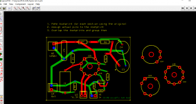
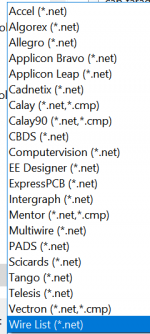
Export and Import Netlist
LTSpice exports netlist to about 20 external layout softwares. Here I share with you the ways. The netlist pin order exported from LTspice is based on the model pins (1, 2, 3,..) order, the pins number must be reassigned in the actual layout footprint as shown. You can add more pins like heaters to the tube model and asy symbol, and they will still be running so long both the model pin and asy pin order are same. You split the original into two half sections, be it twin triode or pentode triode, and make separate footprint for each section and regroup to form group footprint so they're not shift in anyway. Do not change the net order of pin or model. Use text to label the asy model/actual pins so make it easy to reassign later.
LTSpice exports netlist to about 20 external layout softwares. Here I share with you the ways. The netlist pin order exported from LTspice is based on the model pins (1, 2, 3,..) order, the pins number must be reassigned in the actual layout footprint as shown. You can add more pins like heaters to the tube model and asy symbol, and they will still be running so long both the model pin and asy pin order are same. You split the original into two half sections, be it twin triode or pentode triode, and make separate footprint for each section and regroup to form group footprint so they're not shift in anyway. Do not change the net order of pin or model. Use text to label the asy model/actual pins so make it easy to reassign later.
Attachments
Cool stuff, Koonw!
That may safe a lot of drawing time when one intend to build a PCB for a tube amp. 👍
That may safe a lot of drawing time when one intend to build a PCB for a tube amp. 👍
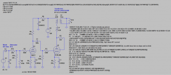
LTSpice phase splitter not working
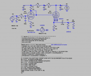
I'm quite new to LTSpice and have only made a few simulations so far. I have drawn a diagram of my (working) driver stage. For some reason the phase inverter doesn't invert in LTSpice. In reality it does...
How do I get a proper simulation of the phase splitter?
Note: the 10M90S in this diagram will be used later on, this code is not needed right now.
Regards, Gerrit
Attachments
Hi,
Is there something like LTSpice for an iPad? I couldn’t find it.
I would like to be able to at least open .asc files with my iPad.
Regards, Gerrit
Is there something like LTSpice for an iPad? I couldn’t find it.
I would like to be able to at least open .asc files with my iPad.
Regards, Gerrit
I'd like to import simulation models of ECC81 and EL84 to a computer that runs Windows 10 and LTSpice. Are there easy step-by-step instructions available?
That question has been asked a number of times. I believe it's been answered previously in this thread.
The following is a long thread, but it should help:
Installing and using LTspice IV (now including LTXVII). From beginner to advanced.
The following is a long thread, but it should help:
Installing and using LTspice IV (now including LTXVII). From beginner to advanced.
The following is a long thread, but it should help:
Installing and using LTspice IV (now including LTXVII). From beginner to advanced.
Okay, thanks!
Seems that post #85 is the one I needed most.
I would like to be able to at least open .asc files with my iPad.
Try using a simple text editor for the various data files
kind regards
Marek
Hi Marek,
Will a text editor show the schematic diagram? I cannot believe that.
Have you tried this?
Regards, Gerrit
Will a text editor show the schematic diagram? I cannot believe that.
Have you tried this?
Regards, Gerrit
No, I don't think it would do that. I was thinking of the symbols and models, rather than the schematics.
kind regards
Marek
kind regards
Marek
Will a text editor show the schematic diagram?
A netlist (which is readable in a text editor) can be generated from the schematic.
Simulating a triode with LTSpice
I have a problem with my simulations. OBVIOUSLY I have done some mistake but I just don't know what. See the screen capture.
It seems that I did not quite catch something, but what is it?
By the way, I copied the ECC81 simulation model from this site:
Spice Model Package 7/7 Triodes | paengdesign
I have a problem with my simulations. OBVIOUSLY I have done some mistake but I just don't know what. See the screen capture.
Port(pin) count mismatch between the definition of subcircuit "nh12at7" and instance: "xu1"
The instance has more connection terminals than the definition.
It seems that I did not quite catch something, but what is it?
By the way, I copied the ECC81 simulation model from this site:
Spice Model Package 7/7 Triodes | paengdesign
Attachments
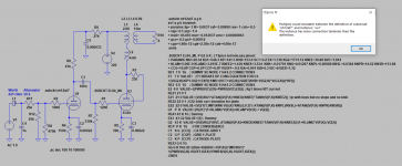
You look as though you have defined the subcircuits twice over - once with the pin parameters (on the right) and once without (next to the x1 and x2 symbols). The symbol has to have the same number of matching net connections as the definition, so the two one liners look to be in conflict with that, at least that is what the error message appears to be saying.
kind regards
Marek
kind regards
Marek
That's one of Duncan Monroe's models. The line "XV1 A G K TRIODENH" is calling that subckt, which wasn't included in your spice directive on your schematic. I have provided the complete model below.I have a problem with my simulations. OBVIOUSLY I have done some mistake but I just don't know what.
Code:
**********************************************************************
* Duncan Amplfication Generic Triode Model (PSpice Implementation)
* Copyright (C)1997-2004 Duncan Amplfication
* Unauthorised Commercial use prohibited
* Please refer to documentation at [url=http://www.duncanamps.com]Duncan's Amp Pages[/url]
*
.SUBCKT TRIODENH A G K
 +PARAMS: LIP=1 LIF=3.7E-3 RAF=18E-3 RAS=1 CDO=0 RAP=4E-3
+ ERP=1.5
+ MU0=17.3 MUR=19E-3 EMC=9.6E-6 GCO=0 GCF=213E-6
+ CGA=3.9p CGK=2.4p CAK=0.7p

************************************************************************
*
* Anode/grid model
*
* Models reduction in mu at large negative grid voltages
* Models change in Ra with negative grid voltages
* Models limit in Ia with high +Vg and low Va
*
* PARAMETERS
*
*    LIP Conduction limit exponent
*    LIF Conduction limit factor
*    CDO Conduction offset
*    RAF Anode resistance factor for neg grid voltages
*    RAP Anode resistance factor for positive grid voltages
*    ERP Emission power
*    MU0 Mu between grid and anode at Vg=0
*    MUR Mu reduction factor for large negative grid voltages
*    EMC Emission coefficient
*    GCO Grid current offset in volts
*    GCF Grid current scale factor
*
************************************************************************

Elim  LI 0  VALUE {PWR(LIMIT(V(A,K),0,1E6),{LIP})*{LIF}}
Egg   GG 0  VALUE {V(G,K)-{CDO}}
Erpf  RP 0  VALUE {1-PWR(LIMIT(-V(GG)*{RAF},0,0.999),{RAS})+LIMIT(V(GG),0,1E6)*{RAP}}
Egr   GR 0  VALUE {LIMIT(V(GG),0,1E6)+LIMIT((V(GG))*(1+V(GG)*{MUR}),0,-1E6)}
Eem   EM 0  VALUE {LIMIT(V(A,K)+V(GR)*{MU0},0,1E6)}
Eep   EP 0  VALUE {PWR(V(EM),ERP)*{EMC}*V(RP)}
Eel   EL 0  VALUE {LIMIT(V(EP),0,V(LI))}
Eld   LD 0  VALUE {LIMIT(V(EP)-V(LI),0,1E6)}
Ga    A  K  VALUE {V(EL)}

************************************************************************
*
* Grid current model
*
* Models grid current, along with rise in grid current at low Va
*
************************************************************************
Egf   GF 0  VALUE {PWR(LIMIT(V(G,K)-{GCO},0,1E6),1.5)*{GCF}}
Gg    G  K  VALUE {(V(GF)+V(LD))}

*
* Capacitances and anti-float resistors
*
CM1    G    K    {CGK}
CM2    A    G    {CGA}
CM3    A    K    {CAK}
RF1    A    0    1000MEG
RF2    G    0    1000MEG
RF3    K    0    1000MEG

.ENDS

**********************************************************************
* GENERIC: 12AT7 / ECC81
* MODEL:   NH12AT7
* NOTES:   No heater model
**********************************************************************
.SUBCKT NH12AT7 A G K
XV1 A G K TRIODENH
+PARAMS: LIP= 1 LIF= 0.0037 RAF= 0.09869 RAS= 1 CDO=-0.5
+ RAP= 0.1 ERP= 1.4
+ MU0= 45.093 MUR= 0.012937 EMC= 0.00000863
+ GCO=-0.5 GCF= 0.00012
+ CGA=1.60E-12 CGK=2.30E-12 CAK=4.00E-13
.ENDSIf you wish you can use my 12AT7 model.
Code:
* ==============================================================
* 12AT7_mz3 (ECC81) LTspice model
* Modified Koren model (8 parameters): mean fit error 0.149064mA
* Traced by Wayne Clay on 3/3/2014 using Curve Captor v0.9.1
* from Mazda Belvu data sheet
* ==============================================================
.subckt 12AT7-mz  P G K
    Bp  P K  I=
+ (0.02790974004m)*uramp(V(P,K)*ln(1.0+(-0.01128450125)+exp((2.13112283)+
+ (2.13112283)*((98.95747475)+(-218.6570898m)*V(G,K))*V(G,K)/sqrt((24.5022294)**2+
+ (V(P,K)-(-33.23286842))**2)))/(2.13112283))**(1.220154214)
    Cgk G K 3.0p ; 0.7p added (2.3p)
    Cgp G P 2.3p ; 0.7p added (1.6p)
    Cpk P K 0.65p ; 0.2p added (0.45p)
    Rpk P K 1.0G ; to avoid floating nodes in mu-follower
    d3  G K dx1
.model dx1 d(is=1n rs=2k cjo=1pf N=1.5 tt=1n)
.ends 12AT7-mzThat problem was solved
Thanks!
I had put the name of the model on the wrong line of the Component Attribute Editor. There were other smaller problems afterwards but they were easily solved. I also used another simulation model for ECC81.
I used the transformer coupling coefficient K = 0.998 but I think it could be 0.999. I haven't measured it so I am not sure.
You look as though you have defined the subcircuits twice over - once with the pin parameters (on the right) and once without (next to the x1 and x2 symbols). The symbol has to have the same number of matching net connections as the definition, so the two one liners look to be in conflict with that, at least that is what the error message appears to be saying.
kind regards
Marek
Thanks!
I had put the name of the model on the wrong line of the Component Attribute Editor. There were other smaller problems afterwards but they were easily solved. I also used another simulation model for ECC81.
I used the transformer coupling coefficient K = 0.998 but I think it could be 0.999. I haven't measured it so I am not sure.
Attachments

Thanks
I may try with that simulation model. Seems that you have tried to achieve high accuracy.
If you wish you can use my 12AT7 model.
I may try with that simulation model. Seems that you have tried to achieve high accuracy.
- Home
- Amplifiers
- Tubes / Valves
- Vacuum Tube SPICE Models