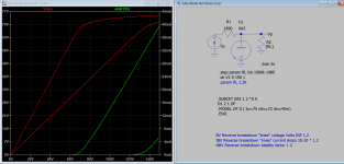
You have S2 in wrong order, below line has been corrected.Hi, looking for assistance with this amp model. Any hints as to why the B+ is so high, I was expecting about 420v from the edcor xpwr144 set at 380v.
.SUBCKT Edcor-xpwr144-380-0-380 P1 P2 S1 S2 CT
I would advice the PSU sim to be excluded, instead assign the correct working voltage to the rest of circuit
Last edited:
Much appreciated. I wouldn’t have uncovered that. I copied and pasted from McLeans spreadsheet as is. I was curious how well the PS sim would be but will take your advice.
Much appreciated. I wouldn’t have uncovered that. I copied and pasted from McLeans spreadsheet as is. I was curious how well the PS sim would be but will take your advice.
Well I mean but you still can test the PSU by plug in the actual current being drawn at each divider, the voltage drop gives the voltage regulation.
Ayumi 6sn7 still takes forever. Can you expand on the “plug in current drawn at divider” statement. Thanks.
1) The ports Speaker_out is duplicated. 2) No grid bias voltages
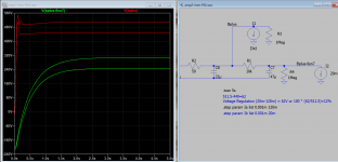
I attached the simplified working version for your review.
After you satisfied with Bplus-6sn7 and Bplus then you run PSU only circuit and insert these values into the Spice directive:
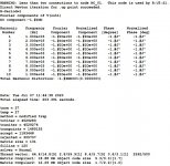
.step param Ia list 0.001m 120m
where Ia is 0.0001m no-load and 120m is Bplus current and 20m is Bplus-6sn7. Then compute the regulation: 511.5-449.9=62
Voltage Regulation (20m-120m) = 62V or 100 * (62/511.5)=12%
I attached the simplified working version for your review.
After you satisfied with Bplus-6sn7 and Bplus then you run PSU only circuit and insert these values into the Spice directive:
.step param Ia list 0.001m 120m
where Ia is 0.0001m no-load and 120m is Bplus current and 20m is Bplus-6sn7. Then compute the regulation: 511.5-449.9=62
Voltage Regulation (20m-120m) = 62V or 100 * (62/511.5)=12%
Attachments
Last edited:
In my physical amp I use the voltage at the 300b anode is 416v and at the anode after the dropping resistor leaving close to 300v for the 6sn7. The current across the 300b cathode resistor with the 65v voltage drop comes at at approximately 87ma. Can you tell me what the 60v on the grid is to sim?
In my physical amp I use the voltage at the 300b anode is 416v and at the anode after the dropping resistor leaving close to 300v for the 6sn7. The current across the 300b cathode resistor with the 65v voltage drop comes at at approximately 87ma. Can you tell me what the 60v on the grid is to sim?
Then -60v (fixed) is not needed, just ground the bias resistor , the self bias will give the right operating point (about -67v and 89mA) . The output is ~9W. So you need to lower the PSU voltages somewhere to sim again.
Hi folks-I have poked around a lot of the pages here and I haven't seen it-can anyone share a link or tutorial on how to get the Tube models to show up in LTSpice on a Mac? I'm brand new to LTspice, and I see that the Ayumi models are in an .inc format and everything in the lib/sym is in .asy format.
Is there any way to get all these models in to the standard library so they are always available when I start a new project? Thank you all so much-and again I'm sorry for asking here-I'm sure this question has probably been asked and answered 1000 times in this 250+ page (!!!) thread, but I've missed it so far.
Is there any way to get all these models in to the standard library so they are always available when I start a new project? Thank you all so much-and again I'm sorry for asking here-I'm sure this question has probably been asked and answered 1000 times in this 250+ page (!!!) thread, but I've missed it so far.
I'm not using Mac. Here is what I found:
1) Put the all tube models symbol and lib or inc in their respective folders e.g
/Users/XXX/Library/Application Support/LTspice/Lib/sym
/Users/XXX/Library/Application Support/LTspice/Lib/cmp
/Users/XXX/Library/Application Support/LTspice/Lib/sub
Or put them in pen drive volume and set search path for asy file and lib/inc files. In Windows one can add extra search paths under Tool->Control Panel.
2) Visit MacSpice - User's Guide (2)
2.5 COMBINING FILES: .INCLUDE LINES
General form:
.INCLUDE filename
Examples:
.INCLUDE /users/spice/common/wattmeter.cir
Frequently, portions of circuit descriptions will be reused in several input files, particularly with common models and subcircuits. In any Spice input file, the '.INCLUDE' line may be used to copy some other file as if that second file appeared in place of the '.INCLUDE' line in the original file. There is no restriction on the file name imposed by Spice beyond those imposed by the local operating system. When the statement does not specify an absolute path for the file, the directories specified by the variable sourcepath are searched.
sourcepath
A list of the directories to search when a source command is given. The default is the current directory and the standard Spice library (/usr/local/lib/spice, or whatever LIBPATH is #defined to in the Spice 3 source).
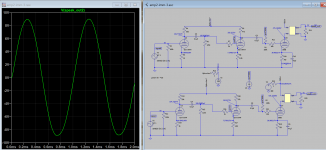
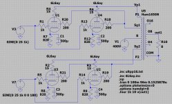
Guys, I need help with a sim problem. This circuit runs fine when connected as pentode or triode, but not in UL (as shown).
In UL it does the dc just fine and all voltages/currents are correct. When running the tran, it runs for over 200 seconds (in pentode it takes 20 sec). It does finish the sim, but then there is no waveform anywhere except at the input (V1). Every other node shows blank (not a zero line, just no trace at all). Even at the right side of R1 there is nothing, even though the left end of R1 has the input signal.
Any help appreciated.
Attachments
Thanks, no, it shouldn't take forever. As I said above, takes 20 seconds when running the pentode version. Same circuit, same everything.
Anyway, that's not the issue. I don't care how long it takes, I just need it to run correctly.
Anyway, that's not the issue. I don't care how long it takes, I just need it to run correctly.
I have drawn a working version, I can't see what's wrong, there is a warning in the spice.log in mine same as yours. Probably the sim is terminated due to lack of convergence, that is it's able to reach target result and the cpu usage is intensive, temperature fan is on. Shouldn't let it run like that, it may harm your computer.
Attachments
Last edited:
- Home
- Amplifiers
- Tubes / Valves
- Vacuum Tube SPICE Models