6N2P SPICE model
Does anyone have a good SPICE model for the 6N2P? I searched the forum but didn't see one (sorry if one is here and I missed it).
Thanks.
Does anyone have a good SPICE model for the 6N2P? I searched the forum but didn't see one (sorry if one is here and I missed it).
Thanks.
Looks very similar to a 12AX7. Transconductance might be a little bit more new 2.1mA/V and after 5000 hours 1.4mA/V. With a mu of 100 the plate resistance might be a tad lower compared to 12AX7 because of the slightly higher transconductance spec. The input capacitance looks to be slightly higher compared to the 12AX7.
It's a spice simulation so I am willing to bet a 12AX7 is fine for a close approximation.
It's a spice simulation so I am willing to bet a 12AX7 is fine for a close approximation.
Looks very similar to a 12AX7. Transconductance might be a little bit more new 2.1mA/V and after 5000 hours 1.4mA/V. With a mu of 100 the plate resistance might be a tad lower compared to 12AX7 because of the slightly higher transconductance spec. The input capacitance looks to be slightly higher compared to the 12AX7.
It's a spice simulation so I am willing to bet a 12AX7 is fine for a close approximation.
Thanks. I have a number of reasonable models for the 12AX7 and could use them, but the application is in a frequency shaping circuit where capacitance values, etc. might be significant enough to matter (or maybe not!). There is probably an Ayumi model somewhere but I haven't been able to find it. A model based on curve tracing would also be good. I've had good results with the Tunnah models, which are based on Curve Captor; there just aren't very many of them.
EML520B SPICE Model
1) The 520B (output tube): 520B-V2 and 520B-V3 Data sheet Emission Labs.
Code:
*
* Generic triode model: EML520B_AN
* Copyright 2003--2008 by Ayumi Nakabayashi, All rights reserved.
* Version 3.10, Generated on Fri Mar 27 23:21:36 2015
*                  Plate
*                  | Grid
*                  | | Cathode
*                  | | |
.SUBCKT EML520B_AN A G K
BGG   GG   0 V=V(G,K)+-1
BM1   M1   0 V=(0.077301771*(URAMP(V(A,K))+1e-10))**-0.57593173
BM2   M2   0 V=(0.72256711*(URAMP(V(GG)+URAMP(V(A,K))/3.588959)+1e-10))**2.0759317
BP    P    0 V=0.0018888741*(URAMP(V(GG)+URAMP(V(A,K))/4.9669559)+1e-10)**1.5
BIK   IK   0 V=U(V(GG))*V(P)+(1-U(V(GG)))*0.0010883699*V(M1)*V(M2)
BIG   IG   0 V=0.00094443704*URAMP(V(G,K))**1.5*(URAMP(V(G,K))/(URAMP(V(A,K))+URAMP(V(G,K)))*1.2+0.4)
BIAK  A    K I=URAMP(V(IK,IG)-URAMP(V(IK,IG)-(0.0015426833*URAMP(V(A,K))**1.5)))+1e-10*V(A,K)
BIGK  G    K I=V(IG)
* CAPS
CGA   G    A 15p
CGK   G    K 8.5p
CAK   A    K 4.1p
.ENDSGU-81 SPICE Models
The control grid current for the pentode isn't modelled too well, but as long as you operate in A1 or AB1, the model should be usable.
Triode-connected:
Pentode:
The control grid current for the pentode isn't modelled too well, but as long as you operate in A1 or AB1, the model should be usable.
Triode-connected:
Code:
*
* Generic triode model: GU-81_T_AN
* Copyright 2003--2008 by Ayumi Nakabayashi, All rights reserved.
* Version 3.10, Generated on Sat Mar 28 10:51:14 2015
*                  Plate
*                  | Grid
*                  | | Cathode
*                  | | |
.SUBCKT GU-81_T_AN A G K
BGG   GG   0 V=V(G,K)+0.99999992
BM1   M1   0 V=(0.034388587*(URAMP(V(A,K))+1e-10))**-0.172136
BM2   M2   0 V=(0.89705622*(URAMP(V(GG)+URAMP(V(A,K))/2.9935449)+1e-10))**1.672136
BP    P    0 V=0.00062411646*(URAMP(V(GG)+URAMP(V(A,K))/3.3370761)+1e-10)**1.5
BIK   IK   0 V=U(V(GG))*V(P)+(1-U(V(GG)))*0.00042995203*V(M1)*V(M2)
BIG   IG   0 V=0.00031205823*URAMP(V(G,K))**1.5*(URAMP(V(G,K))/(URAMP(V(A,K))+URAMP(V(G,K)))*1.2+0.4)
BIAK  A    K I=URAMP(V(IK,IG)-URAMP(V(IK,IG)-(0.00061266557*URAMP(V(A,K))**1.5)))+1e-10*V(A,K)
BIGK  G    K I=V(IG)
* CAPS
CGA   G    A 0.1p
CGK   G    K 29p
CAK   A    K 24p
.ENDS
Pentode:
Code:
*
* Generic pentode model: GU-81_AN
* Copyright 2003--2008 by Ayumi Nakabayashi, All rights reserved.
* Version 3.10, Generated on Sat Mar 28 11:21:42 2015
*                Plate
*                | Screen Grid
*                | |  Control Grid
*                | |  |  Cathode
*                | |  |  |
.SUBCKT GU-81_AN A G2 G1 K
BGG   GG   0 V=V(G1,K)+0.99999992
BM1   M1   0 V=(0.034388587*(URAMP(V(G2,K))+1e-10))**-0.172136
BM2   M2   0 V=(0.89705622*(URAMP(V(GG)+URAMP(V(G2,K))/2.9935449)))**1.672136
BP    P    0 V=0.00062411646*(URAMP(V(GG)+URAMP(V(G2,K))/3.3370761))**1.5
BIK   IK   0 V=U(V(GG))*V(P)+(1-U(V(GG)))*0.00042995203*V(M1)*V(M2)
BIG   IG   0 V=0.00031205823*URAMP(V(G1,K))**1.5*(URAMP(V(G1,K))/(URAMP(V(A,K))+URAMP(V(G1,K)))*1.2+0.4)
BIK2  IK2  0 V=V(IK,IG)*(1-0.4*(EXP(-URAMP(V(A,K))/URAMP(V(G2,K))*15)-EXP(-15)))
BIG2T IG2T 0 V=V(IK2)*(0.77319652*(1-URAMP(V(A,K))/(URAMP(V(A,K))+10))**1.5+0.22680348)
BIK3  IK3  0 V=V(IK2)*(URAMP(V(A,K))+8520)/(URAMP(V(G2,K))+8520)
BIK4  IK4  0 V=V(IK3)-URAMP(V(IK3)-(0.00061266557*(URAMP(V(A,K))+URAMP(URAMP(V(G2,K))-URAMP(V(A,K))))**1.5))
BIP   IP   0 V=URAMP(V(IK4,IG2T)-URAMP(V(IK4,IG2T)-(0.00061266557*URAMP(V(A,K))**1.5)))
BIAK  A    K I=V(IP)+1e-10*V(A,K)
BIG2  G2   K I=URAMP(V(IK4,IP))
BIGK  G1   K I=V(IG)
* CAPS
CGA   G1  A  0.1p
CGK   G1  K  17.4p
C12   G1  G2 11.6p
CAK   A   K  24p
.ENDS6N2P SPICE Model
Yes, upon closer inspection, the 6N2P is different enough from the 12AX7 to warrant its own model, I had to use Curve Captor this time since Ayumi's model was very poor by comparison. The positive grid current is not modelled by the Curve Captor, so try not to use Eg<-0.6V.
... might be significant enough to matter (or maybe not!). There is probably an Ayumi model somewhere but I haven't been able to find it.
Yes, upon closer inspection, the 6N2P is different enough from the 12AX7 to warrant its own model, I had to use Curve Captor this time since Ayumi's model was very poor by comparison. The positive grid current is not modelled by the Curve Captor, so try not to use Eg<-0.6V.
Code:
* 6N2P Spice 3F4 model
* Generated With Curve Captor
* by: jazbo8 Sat, Mar 28, 2015 12:42:30 PM
.SUBCKT 6N2P A G K
Bp  A K  I=(0.03356391743m)*uramp(V(A,K)*ln(1.0+(-0.002087327735)+exp((2.881700742)+(2.881700742)*((127.0402396)
++(-5791.662541m)*V(G,K))*V(G,K)/sqrt((65.63583491)**2+(V(A,K)-(8.436596032))**2)))/(2.881700742))**(0.9333315014)
* CAPS
CGA   G    A 0.7p
CGK   G    K 2.25p
CAK   A    K 2.3p
.ENDSEML20B SPICE Model
You are welcome, here is the EML20B model, since no data was provided for the capacitances, I just took a wild guess.
Hi jazbo8 - thanks very much for the 520 model, most helpful! Looks to be working well.
You are welcome, here is the EML20B model, since no data was provided for the capacitances, I just took a wild guess.
Code:
*
* Generic triode model: EML20B_AN
* Copyright 2003--2008 by Ayumi Nakabayashi, All rights reserved.
* Version 3.10, Generated on Sat Mar 28 13:34:34 2015
*                 Plate
*                 | Grid
*                 | | Cathode
*                 | | |
.SUBCKT EML20B_AN A G K
BGG   GG   0 V=V(G,K)+-1
BM1   M1   0 V=(0.002336905*(URAMP(V(A,K))+1e-10))**-0.07239753
BM2   M2   0 V=(0.95395724*(URAMP(V(GG)+URAMP(V(A,K))/19.702455)+1e-10))**1.5723975
BP    P    0 V=0.00094670443*(URAMP(V(GG)+URAMP(V(A,K))/20.653394)+1e-10)**1.5
BIK   IK   0 V=U(V(GG))*V(P)+(1-U(V(GG)))*0.00076017337*V(M1)*V(M2)
BIG   IG   0 V=0.00047335221*URAMP(V(G,K))**1.5*(URAMP(V(G,K))/(URAMP(V(A,K))+URAMP(V(G,K)))*1.2+0.4)
BIAK  A    K I=URAMP(V(IK,IG)-URAMP(V(IK,IG)-(0.00054293446*URAMP(V(A,K))**1.5)))+1e-10*V(A,K)
BIGK  G    K I=V(IG)
* CAPS
CGA   G    A 15p
CGK   G    K 8.5p
CAK   A    K 4p
.ENDS60FX5 SPICE Models
Triode-connected:
Pentode:
Triode-connected:
Code:
*
* Generic triode model: 60FX5_T_AN
* Copyright 2003--2008 by Ayumi Nakabayashi, All rights reserved.
* Version 3.10, Generated on Sat Mar 28 13:40:14 2015
*                  Plate
*                  | Grid
*                  | | Cathode
*                  | | |
.SUBCKT 60FX5_T_AN A G K
BGG   GG   0 V=V(G,K)+0.2939741
BM1   M1   0 V=(0.036895604*(URAMP(V(A,K))+1e-10))^-1.1027592
BM2   M2   0 V=(0.57631148*(URAMP(V(GG)+URAMP(V(A,K))/11.483442)+1e-10))^2.6027592
BP    P    0 V=0.0079725151*(URAMP(V(GG)+URAMP(V(A,K))/19.925756)+1e-10)^1.5
BIK   IK   0 V=U(V(GG))*V(P)+(1-U(V(GG)))*0.0056787803*V(M1)*V(M2)
BIG   IG   0 V=0.0039862575*URAMP(V(G,K))^1.5*(URAMP(V(G,K))/(URAMP(V(A,K))+URAMP(V(G,K)))*1.2+0.4)
BIAK  A    K I=URAMP(V(IK,IG)-URAMP(V(IK,IG)-(0.0045938923*URAMP(V(A,K))^1.5)))+1e-10*V(A,K)
BIGK  G    K I=V(IG)
* CAPS
CGA   G    A 0.65p
CGK   G    K 17p
CAK   A    K 9p
.ENDS
Pentode:
Code:
*
* Generic pentode model: 60FX5_AN
* Copyright 2003--2008 by Ayumi Nakabayashi, All rights reserved.
* Version 3.10, Generated on Sun Mar 22 18:25:35 2015
*                Plate
*                | Screen Grid
*                | |  Control Grid
*                | |  |  Cathode
*                | |  |  |
.SUBCKT 60FX5_AN A G2 G1 K
BGG   GG   0 V=V(G1,K)+0.2939741
BM1   M1   0 V=(0.036895604*(URAMP(V(G2,K))+1e-10))**-1.1027592
BM2   M2   0 V=(0.57631148*(URAMP(V(GG)+URAMP(V(G2,K))/11.483442)))**2.6027592
BP    P    0 V=0.0079725151*(URAMP(V(GG)+URAMP(V(G2,K))/19.925756))**1.5
BIK   IK   0 V=U(V(GG))*V(P)+(1-U(V(GG)))*0.0056787803*V(M1)*V(M2)
BIG   IG   0 V=0.0039862575*URAMP(V(G1,K))**1.5*(URAMP(V(G1,K))/(URAMP(V(A,K))+URAMP(V(G1,K)))*1.2+0.4)
BIK2  IK2  0 V=V(IK,IG)*(1-0.4*(EXP(-URAMP(V(A,K))/URAMP(V(G2,K))*15)-EXP(-15)))
BIG2T IG2T 0 V=V(IK2)*(0.80072708*(1-URAMP(V(A,K))/(URAMP(V(A,K))+10))**1.5+0.19927292)
BIK3  IK3  0 V=V(IK2)*(URAMP(V(A,K))+857)/(URAMP(V(G2,K))+857)
BIK4  IK4  0 V=V(IK3)-URAMP(V(IK3)-(0.0045938923*(URAMP(V(A,K))+URAMP(URAMP(V(G2,K))-URAMP(V(A,K))))**1.5))
BIP   IP   0 V=URAMP(V(IK4,IG2T)-URAMP(V(IK4,IG2T)-(0.0045938923*URAMP(V(A,K))**1.5)))
BIAK  A    K I=V(IP)+1e-10*V(A,K)
BIG2  G2   K I=URAMP(V(IK4,IP))
BIGK  G1   K I=V(IG)
* CAPS
CGA   G1  A  0.65p
CGK   G1  K  10.2p
C12   G1  G2 6.8p
CAK   A   K  9p
.ENDSEL91 SPICE Models
Triode-connected:
Pentode:
just curious is there a EL91 amongst models ?
Triode-connected:
Code:
*
* Generic triode model: EL91_T_AN
* Copyright 2003--2008 by Ayumi Nakabayashi, All rights reserved.
* Version 3.10, Generated on Sat Mar 28 13:59:08 2015
*                 Plate
*                 | Grid
*                 | | Cathode
*                 | | |
.SUBCKT EL91_T_AN A G K
BGG   GG   0 V=V(G,K)+0.37812741
BM1   M1   0 V=(0.052842603*(URAMP(V(A,K))+1e-10))**-1.2200696
BM2   M2   0 V=(0.55145648*(URAMP(V(GG)+URAMP(V(A,K))/8.4882936)+1e-10))**2.7200696
BP    P    0 V=0.001206989*(URAMP(V(GG)+URAMP(V(A,K))/15.3925)+1e-10)**1.5
BIK   IK   0 V=U(V(GG))*V(P)+(1-U(V(GG)))*0.00093811259*V(M1)*V(M2)
BIG   IG   0 V=0.00060349451*URAMP(V(G,K))**1.5*(URAMP(V(G,K))/(URAMP(V(A,K))+URAMP(V(G,K)))*1.2+0.4)
BIAK  A    K I=URAMP(V(IK,IG)-URAMP(V(IK,IG)-(0.00072300583*URAMP(V(A,K))**1.5)))+1e-10*V(A,K)
BIGK  G    K I=V(IG)
* CAPS
CGA   G    A 0.3p
CGK   G    K 3.7p
CAK   A    K 4p
.ENDS
Pentode:
Code:
*
* Generic pentode model: EL91_AN
* Copyright 2003--2008 by Ayumi Nakabayashi, All rights reserved.
* Version 3.10, Generated on Sat Mar 28 14:27:53 2015
*               Plate
*               | Screen Grid
*               | |  Control Grid
*               | |  |  Cathode
*               | |  |  |
.SUBCKT EL91_AN A G2 G1 K
BGG   GG   0 V=V(G1,K)+0.33467138
BM1   M1   0 V=(0.041540361*(URAMP(V(G2,K))+1e-10))**-0.88028556
BM2   M2   0 V=(0.63017649*(URAMP(V(GG)+URAMP(V(G2,K))/8.9027514)))**2.3802856
BP    P    0 V=0.0011525402*(URAMP(V(GG)+URAMP(V(G2,K))/14.127394))**1.5
BIK   IK   0 V=U(V(GG))*V(P)+(1-U(V(GG)))*0.00072093882*V(M1)*V(M2)
BIG   IG   0 V=0.00057627008*URAMP(V(G1,K))**1.5*(URAMP(V(G1,K))/(URAMP(V(A,K))+URAMP(V(G1,K)))*1.2+0.4)
BIK2  IK2  0 V=V(IK,IG)*(1-0.4*(EXP(-URAMP(V(A,K))/URAMP(V(G2,K))*15)-EXP(-15)))
BIG2T IG2T 0 V=V(IK2)*(0.88096197*(1-URAMP(V(A,K))/(URAMP(V(A,K))+10))**1.5+0.11903803)
BIK3  IK3  0 V=V(IK2)*(URAMP(V(A,K))+2870)/(URAMP(V(G2,K))+2870)
BIK4  IK4  0 V=V(IK3)-URAMP(V(IK3)-(0.00070078362*(URAMP(V(A,K))+URAMP(URAMP(V(G2,K))-URAMP(V(A,K))))**1.5))
BIP   IP   0 V=URAMP(V(IK4,IG2T)-URAMP(V(IK4,IG2T)-(0.00070078362*URAMP(V(A,K))**1.5)))
BIAK  A    K I=V(IP)+1e-10*V(A,K)
BIG2  G2   K I=URAMP(V(IK4,IP))
BIGK  G1   K I=V(IG)
* CAPS
CGA   G1  A  0.3p
CGK   G1  K  2.2p
C12   G1  G2 1.5p
CAK   A   K  4p
.ENDSYes, upon closer inspection, the 6N2P is different enough from the 12AX7 to warrant its own model, I had to use Curve Captor this time since Ayumi's model was very poor by comparison. The positive grid current is not modelled by the Curve Captor, so try not to use Eg<-0.6V.
Thanks!
Hi jazbo8, thanks a lot! 🙂 The 60FX5 model was working great with LTSpice! I am trying to build a small SE or PP amp using 60FX5. Thanks again for your helps!http://www.diyaudio.com/forums/members/jazbo8.html
Hi jazbo8, thanks very much for the EML20B model too! 🙂
The only thing I did notice with the 520B you did for me first, in my Spice model the mu (amplification factor) seems a little low? The output is giving me about 3.5x the voltage swing at input, whereas EML specify the mu to be more like 5.6 at their recommended operating point.
It could me that I'm doing something wrong though, or maybe the actual curves tell a different story.
The 20B driver tube model is fine in this respect though.
Thanks.
6EM5 Pentode SPICE Model
You are welcome, here is the pentode model for 6EM5, no triode-connected model though since I have nothing to compare it against.
Pentode:
Hi jazbo8, thanks a lot! 🙂 The 60FX5 model was working great with LTSpice! I am trying to build a small SE or PP amp using 60FX5. Thanks again for your helps!
You are welcome, here is the pentode model for 6EM5, no triode-connected model though since I have nothing to compare it against.
Pentode:
Code:
*
* Generic pentode model: 6EM5_AN
* Copyright 2003--2008 by Ayumi Nakabayashi, All rights reserved.
* Version 3.10, Generated on Sun Mar 29 11:14:40 2015
*               Plate
*               | Screen Grid
*               | |  Control Grid
*               | |  |  Cathode
*               | |  |  |
.SUBCKT 6EM5_AN A G2 G1 K
BGG   GG   0 V=V(G1,K)+-0.625
BM1   M1   0 V=(0.067724458*(URAMP(V(G2,K))+1e-10))**-1.1666667
BM2   M2   0 V=(0.5625*(URAMP(V(GG)+URAMP(V(G2,K))/6.46)))**2.6666667
BP    P    0 V=0.0022121734*(URAMP(V(GG)+URAMP(V(G2,K))/11.484444))**1.5
BIK   IK   0 V=U(V(GG))*V(P)+(1-U(V(GG)))*0.00165*V(M1)*V(M2)
BIG   IG   0 V=0.0011060867*URAMP(V(G1,K))**1.5*(URAMP(V(G1,K))/(URAMP(V(A,K))+URAMP(V(G1,K)))*1.2+0.4)
BIK2  IK2  0 V=V(IK,IG)*(1-0.4*(EXP(-URAMP(V(A,K))/URAMP(V(G2,K))*15)-EXP(-15)))
BIG2T IG2T 0 V=V(IK2)*(0.9373*(1-URAMP(V(A,K))/(URAMP(V(A,K))+10))**1.5+0.0627)
BIK3  IK3  0 V=V(IK2)*(URAMP(V(A,K))+2750)/(URAMP(V(G2,K))+2750)
BIK4  IK4  0 V=V(IK3)-URAMP(V(IK3)-(0.0014012231*(URAMP(V(A,K))+URAMP(URAMP(V(G2,K))-URAMP(V(A,K))))**1.5))
BIP   IP   0 V=URAMP(V(IK4,IG2T)-URAMP(V(IK4,IG2T)-(0.0014012231*URAMP(V(A,K))**1.5)))
BIAK  A    K I=V(IP)+1e-10*V(A,K)
BIG2  G2   K I=URAMP(V(IK4,IP))
BIGK  G1   K I=V(IG)
* CAPS
CGA   G1  A  0.7p
CGK   G1  K  6p
C12   G1  G2 4p
CAK   A   K  5.1p
.ENDSThe model for the 520B should be pretty accurate, provided that the data supplied by Emission Labs is the same one that it used for the recommeded operating conditions, the best thing to do, is to breadboard it and run some quick tests to verify the actual performance. In any case, below is the load line using the SPICE model, the Po is about 5W short of the spec...The only thing I did notice with the 520B you did for me first, in my Spice model the mu (amplification factor) seems a little low? The output is giving me about 3.5x the voltage swing at input, whereas EML specify the mu to be more like 5.6 at their recommended operating point.
An externally hosted image should be here but it was not working when we last tested it.
Last edited:
6AS5 Pentode SPICE Model
Code:
*
* Generic pentode model: 6AS5_AN
* Copyright 2003--2008 by Ayumi Nakabayashi, All rights reserved.
* Version 3.10, Generated on Sun Mar 29 16:56:29 2015
*               Plate
*               | Screen Grid
*               | |  Control Grid
*               | |  |  Cathode
*               | |  |  |
.SUBCKT 6AS5_AN A G2 G1 K
BGG   GG   0 V=V(G1,K)+0.68558078
BM1   M1   0 V=(0.06789648*(URAMP(V(G2,K))+1e-10))**-0.71390806
BM2   M2   0 V=(0.67753491*(URAMP(V(GG)+URAMP(V(G2,K))/4.7493639)))**2.2139081
BP    P    0 V=0.0016148884*(URAMP(V(GG)+URAMP(V(G2,K))/7.00977))**1.5
BIK   IK   0 V=U(V(GG))*V(P)+(1-U(V(GG)))*0.00095048131*V(M1)*V(M2)
BIG   IG   0 V=0.00080744418*URAMP(V(G1,K))**1.5*(URAMP(V(G1,K))/(URAMP(V(A,K))+URAMP(V(G1,K)))*1.2+0.4)
BIK2  IK2  0 V=V(IK,IG)*(1-0.4*(EXP(-URAMP(V(A,K))/URAMP(V(G2,K))*15)-EXP(-15)))
BIG2T IG2T 0 V=V(IK2)*(0.929471362*(1-URAMP(V(A,K))/(URAMP(V(A,K))+10))**1.5+0.070528638)
BIK3  IK3  0 V=V(IK2)*(URAMP(V(A,K))+1108.75)/(URAMP(V(G2,K))+1108.75)
BIK4  IK4  0 V=V(IK3)-URAMP(V(IK3)-(0.0011650554*(URAMP(V(A,K))+URAMP(URAMP(V(G2,K))-URAMP(V(A,K))))**1.5))
BIP   IP   0 V=URAMP(V(IK4,IG2T)-URAMP(V(IK4,IG2T)-(0.0011650554*URAMP(V(A,K))**1.5)))
BIAK  A    K I=V(IP)+1e-10*V(A,K)
BIG2  G2   K I=URAMP(V(IK4,IP))
BIGK  G1   K I=V(IG)
* CAPS
CGA   G1  A  0.6p
CGK   G1  K  7.2p
C12   G1  G2 4.8p
CAK   A   K  6.3p
.ENDS13E1 Spice Model
Jazbo8 - we had a discussion about a 13E1 model which you kindly provided in February. At the time you said:
'Here are the SPICE models for the 13E1 based on the sample that you provided, please note that your sample does not seem to match that of the AEI datasheet. The sample's current seems to be a bit lower than the [AEI]datasheet'
To take one operating point Va=200V. Vg=-30V and Ia=262mA from the first batch of tubes I generated triode mode curves from [these are date-stamped 1977 and labelled STC].
I have now tested a second batch of 13E1s [labelled 'ITT' with no date stamp , and slightly different getters but otherwise looking like NOS and as if they came from the same factory] at the same operating point. These gave Ia=243mA minimum and 282mA maximum with for a total of eight tubes average Ia=265mA.
Maybe two different batches of tubes have aged the same way, or maybe the AEI data sheet was wrong! Who knows but the data is consistent and I think the models can be used with confidence.
PE1/100
Looking for LTspice model. Datasheet: http://www.mif.pg.gda.pl/homepages/frank/sheets/030/p/PE1-100.pdf
Looking for LTspice model. Datasheet: http://www.mif.pg.gda.pl/homepages/frank/sheets/030/p/PE1-100.pdf
Cool, that's good to know.Maybe two different batches of tubes have aged the same way, or maybe the AEI data sheet was wrong! Who knows but the data is consistent and I think the models can be used with confidence.
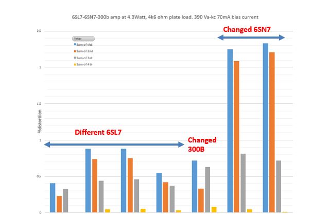
Can anyone please post a utracer plot or model of Tungsol-Reissue 6SL7?. For some reasin the use of that particuar tube reduced the distortion in my 6SL7-6SN7-300b amplifier by 60-70%. ANY other 6SN7 gives much higher distortion. Something magical is going in between the tube curve lines, and I wish Ig coule see tha actula tube curves. You can see the effect of my tube rolling in the figure attached.
- Home
- Amplifiers
- Tubes / Valves
- Vacuum Tube SPICE Models