6P41S SPICE Models
Here are the 6P41S SPICE models from Ayumi:
Triode-Connected:
Pentode:
Here are the 6P41S SPICE models from Ayumi:
Triode-Connected:
Code:
*
* Generic triode model: 6P41S_T_AN
* Copyright 2003--2008 by Ayumi Nakabayashi, All rights reserved.
* Version 3.10, Generated on Fri Mar 20 07:57:10 2015
*                  Plate
*                  | Grid
*                  | | Cathode
*                  | | |
.SUBCKT 6P41S_T_AN A G K
BGG   GG   0 V=V(G,K)+0.1668632
BM1   M1   0 V=(0.072356657*(URAMP(V(A,K))+1e-10))**-0.73823931
BM2   M2   0 V=(0.67016962*(URAMP(V(GG)+URAMP(V(A,K))/4.5583971)+1e-10))**2.2382393
BP    P    0 V=0.0028798695*(URAMP(V(GG)+URAMP(V(A,K))/6.8018557)+1e-10)**1.5
BIK   IK   0 V=U(V(GG))*V(P)+(1-U(V(GG)))*0.0017063703*V(M1)*V(M2)
BIG   IG   0 V=0.0014399347*URAMP(V(G,K))**1.5*(URAMP(V(G,K))/(URAMP(V(A,K))+URAMP(V(G,K)))*1.2+0.4)
BIAK  A    K I=URAMP(V(IK,IG)-URAMP(V(IK,IG)-(0.0020978268*URAMP(V(A,K))**1.5)))+1e-10*V(A,K)
BIGK  G    K I=V(IG)
* CAPS
CGA   G    A 0.5p
CGK   G    K 23p
CAK   A    K 11p
.ENDS
Pentode:
Code:
*
* Generic pentode model: 6P41S_AN
* Copyright 2003--2008 by Ayumi Nakabayashi, All rights reserved.
* Version 3.10, Generated on Fri Mar 20 07:56:32 2015
*                Plate
*                | Screen Grid
*                | |  Control Grid
*                | |  |  Cathode
*                | |  |  |
.SUBCKT 6P41S_AN A G2 G1 K
BGG   GG   0 V=V(G1,K)+0.1668632
BM1   M1   0 V=(0.072356657*(URAMP(V(G2,K))+1e-10))**-0.73823931
BM2   M2   0 V=(0.67016962*(URAMP(V(GG)+URAMP(V(G2,K))/4.5583971)))**2.2382393
BP    P    0 V=0.0028798695*(URAMP(V(GG)+URAMP(V(G2,K))/6.8018557))**1.5
BIK   IK   0 V=U(V(GG))*V(P)+(1-U(V(GG)))*0.0017063703*V(M1)*V(M2)
BIG   IG   0 V=0.0014399347*URAMP(V(G1,K))**1.5*(URAMP(V(G1,K))/(URAMP(V(A,K))+URAMP(V(G1,K)))*1.2+0.4)
BIK2  IK2  0 V=V(IK,IG)*(1-0.4*(EXP(-URAMP(V(A,K))/URAMP(V(G2,K))*15)-EXP(-15)))
BIG2T IG2T 0 V=V(IK2)*(0.970972176*(1-URAMP(V(A,K))/(URAMP(V(A,K))+10))**1.5+0.029027824)
BIK3  IK3  0 V=V(IK2)*(URAMP(V(A,K))+158230)/(URAMP(V(G2,K))+158230)
BIK4  IK4  0 V=V(IK3)-URAMP(V(IK3)-(0.0020978268*(URAMP(V(A,K))+URAMP(URAMP(V(G2,K))-URAMP(V(A,K))))**1.5))
BIP   IP   0 V=URAMP(V(IK4,IG2T)-URAMP(V(IK4,IG2T)-(0.0020978268*URAMP(V(A,K))**1.5)))
BIAK  A    K I=V(IP)+1e-10*V(A,K)
BIG2  G2   K I=URAMP(V(IK4,IP))
BIGK  G1   K I=V(IG)
* CAPS
CGA   G1  A  0.5p
CGK   G1  K  13.8p
C12   G1  G2 9.2p
CAK   A   K  11p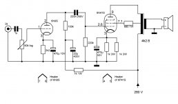
.ENDSI tested your pentode model and it works fine. The results are very similar to my 6P41S SE_UL I have built (attached).
But what is the sense of triode model of a pentode ?
When I build or simulate by using triode connected pentode, I put a resistor between g2 and anode and fine tune this to best linearity.
This can not be done when simulatin with triode model, but in practise that resistor must be there.
Does your pentode model with g2 connected to anode give identical results with triode model ?
Attachments
For the 6P41S, the triode-connected model is redudant and can be discarded, but for many pentodes if you simply connect the screen to the plate using the pentode model in the sim, it will not give you the same characteristic as the triode-connected model, i.e., you will not get the same triode curves shown in the datasheets, this is because many datasheets contain errors, so I have to make some adjustments when using the Ayumi method to build the pentode model. Anyway, for convienence, I make both models available depending how the tube is used in the circuit.But what is the sense of triode model of a pentode? Does your pentode model with g2 connected to anode give identical results with triode model?
Thanks, I have that library too. These models do produce results very similar to the Ayumi models and include the triodes I use most often, so I suppose I really do have what I need for the most part. I'm always looking for something better, though. 🙂
I have tried lots of models with varying results. For me, the most important thing is not that they closely follow the data sheet but rather that they give results close to what I get with real tubes in the actual circuit. The curve captor ones seem the closest too.
Cheers
Ian
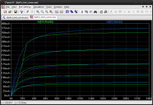
I did this really quickly, seems to be fairly close for screen current and I can't read Cyrillic very well... 😀
Code:.SUBCKT 6P41S 1 4 2 3 ; P G2 G K + PARAMS: CCG=3P CGP=1.4P CCP=1.9P RGI=2000 + MU=91.184 EX=1.3719 KG1=275.0 KG2=4500.0 KP=10.65 KVB=45.0 ; Vp_MAX=420.0 Ip_M AX=0.256 Vg_step=1.0 *-------------------------------------------------- RE1 7 0 1MEG ; DUMMY SO NODE 7 HAS 2 CONNECTIONS E1 7 0 VALUE= ; E1 BREAKS UP LONG EQUATION FOR G1. +{V(4,3)/KP*LN(1+EXP((1/MU+V(2,3)/V(4,3))*KP))} G1 1 3 VALUE={(PWR(V(7),EX)+PWRS(V(7),EX))/KG1*ATAN(V(1,3)/KVB)} *G2 4 3 VALUE={(EXP(EX*(LN((V(4,3)/MU)+V(2,3)))))/KG2} G2 4 3 VALUE={(PWR(V(7),EX)+PWRS(V(7),EX))/KG2*(2.5708-ATAN(V(1,3)/KVB))} RCP 1 3 1G ; FOR CONVERGENCE C1 2 3 {CCG} ; CATHODE-GRID 1 C2 1 2 {CGP} ; GRID 1-PLATE C3 1 3 {CCP} ; CATHODE-PLATE R1 2 5 {RGI} ; FOR GRID CURRENT D3 5 3 DX ; FOR GRID CURRENT .MODEL DX D(IS=1N RS=1 CJO=10PF TT=1N) .ENDS
Thanks, I have tryed it and it do work quite accurate when compare sheet.
But I need a model for the 6J51P who is a small penthode, and I do not now much about make models, however yours can easely be changed? if I have datasheet of tube.
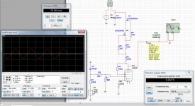
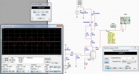
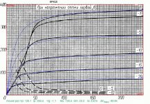
The 6J41 is a powertube, and the 6J51 a voltage amp. Picture two is de sim with a 6J6P tube who work fine in triode connection.
Thanks for the data.
kees
Attachments
Hmm, how can it be close to the datasheet when cogsncogs already told us that the currents are way off...Thanks, I have tryed it and it do work quite accurate when compare sheet.
Hmm, how can it be close to the datasheet when cogsncogs already told us that the currents are way off...
It is far from this specs: https://www.dropbox.com/s/9pjwtmosyk09xdk/6p41s.pdf?dl=0
But the model jazbo8 posted is very accurately according to attached 6P41S specs.
Thanks again.
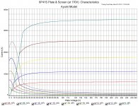
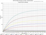
It looks like my use of 300V on the screens yesterday (like in the RCA 7868 data sheet) was misguided. Here's how the two models compare with 170V on the screens (like your data sheet's, right?) The Ayumi does look significantly more accurate.
It is far from this specs: https://www.dropbox.com/s/9pjwtmosyk09xdk/6p41s.pdf?dl=0
But the model jazbo8 posted is very accurately according to attached 6P41S specs.
Thanks again.
Attachments
Hmm, how can it be close to the datasheet when cogsncogs already told us that the currents are way off...
I did look at the sheet and it was close, or I did miss something.
Okay, this is as close as I'm going to get matching a Koren model to the plate curves from the data sheet using Model Paint Tools at least for now. 😛
Funny, why does it say paint_kit.jar? I used paint_kip! Maybe change the name to pain_kit... 😀
Code:
**** 6P41S ******************************************
* Created on 03/20/2015 15:33 using paint_kit.jar 2.6
* www.dmitrynizh.com/tubeparams_image.htm
* Plate Curves image file: 6p41s.gif
* Data source link: http://next-tube.com/DataSheets/tubes/6p41s.djvu
*----------------------------------------------------------------------------------
.SUBCKT 6P41S 1 4 2 3 ; P G2 G K
+ PARAMS: CCG=13.8P  CGP=0.5P CCP=11.0P CGG2=9.2P RGI=2000
+ MU=21.1 KG1=271.0 KP=13.8 KVB=12.4 EX=1.36 KG2=5000
* Vp_MAX=240 Ip_MAX=400 Vg_step=5 Vg_start=0 Vg_count=5
* Rp=1600 Vg_ac=23.5 P_max=7.5 Vg_qui=-23.4 Vp_qui=240 UL=0.43 EG2=170
* X_MIN=36 Y_MIN=24 X_SIZE=733 Y_SIZE=488 FSZ_X=1300 FSZ_Y=685 XYGrid=false
* showLoadLine=n showIp=y isDHT=n isPP=n isAsymPP=n isUL=n showDissipLimit=n
* showIg1=n gridLevel2=n isInputSnapped=n
* XYProjections=n harmonicPlot=y harmonics=y
*----------------------------------------------------------------------------------
RE1  7 0  1MEG    ; DUMMY SO NODE 7 HAS 2 CONNECTIONS
E1   7 0  VALUE=  ; E1 BREAKS UP LONG EQUATION FOR G1.
+{V(4,3)/KP*LN(1+EXP((1/MU+V(2,3)/V(4,3))*KP))}
G1   1 3  VALUE={(PWR(V(7),EX)+PWRS(V(7),EX))/KG1*ATAN(V(1,3)/KVB)}
*G2   4 3  VALUE={(EXP(EX*(LN((V(4,3)/MU)+V(2,3)))))/KG2}
G2   4 3 VALUE={(PWR(V(7),EX)+PWRS(V(7),EX))/KG2*(2.5708-ATAN(V(1,3)/KVB))}
RCP  1 3  1G      ; FOR CONVERGENCE
C1   2 3  {CCG}    ; CATHODE-GRID 1
C2   1 2  {CGP}  ; GRID 1-PLATE
C3   1 3  {CCP}   ; CATHODE-PLATE
C4   2 4  {CGG2}  ; GRID-SCREEN
R1   2 5  {RGI}   ; FOR GRID CURRENT
D3   5 3  DX      ; FOR GRID CURRENT
.MODEL DX D(IS=1N RS=1 CJO=10PF TT=1N)
.ENDS
*$Attachments
Hello guys,
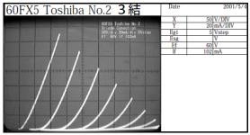
I am looking for LTSpice models for 6BK5, 6AS5, 6DS5, 60FX5 and 6EM5.
Is anyone able ( and kind ) enough to make LT Spice model for those tubes ?
Many thanks!
I am looking for LTSpice models for 6BK5, 6AS5, 6DS5, 60FX5 and 6EM5.
Is anyone able ( and kind ) enough to make LT Spice model for those tubes ?
Many thanks!
If you can provide the triode-connected curves, I can take a crack at making the models for them.Hello guys,
I am looking for LTSpice models for 6BK5, 6AS5, 6DS5, 60FX5 and 6EM5.
Is anyone able ( and kind ) enough to make LT Spice model for those tubes ?
Many thanks!
6BK5 SPICE Models
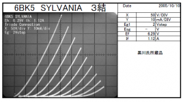
Triode-Connected (based on the Sylvania data supplied):
Pentode (adjusted to the GE datasheet):
Triode-Connected (based on the Sylvania data supplied):
Code:
*
* Generic triode model: 6BK5_T_AN
* Copyright 2003--2008 by Ayumi Nakabayashi, All rights reserved.
* Version 3.10, Generated on Sun Mar 22 10:42:01 2015
*                 Plate
*                 | Grid
*                 | | Cathode
*                 | | |
.SUBCKT 6BK5_T_AN A G K
BGG   GG   0 V=V(G,K)+0.28498004
BM1   M1   0 V=(0.019472057*(URAMP(V(A,K))+1e-10))**-0.81253226
BM2   M2   0 V=(0.6486396*(URAMP(V(GG)+URAMP(V(A,K))/18.044339)+1e-10))**2.3125323
BP    P    0 V=0.0037780919*(URAMP(V(GG)+URAMP(V(A,K))/27.818744)+1e-10)**1.5
BIK   IK   0 V=U(V(GG))*V(P)+(1-U(V(GG)))*0.0022958065*V(M1)*V(M2)
BIG   IG   0 V=0.001889046*URAMP(V(G,K))**1.5*(URAMP(V(G,K))/(URAMP(V(A,K))+URAMP(V(G,K)))*1.2+0.4)
BIAK  A    K I=URAMP(V(IK,IG)-URAMP(V(IK,IG)-(0.0020945824*URAMP(V(A,K))**1.5)))+1e-10*V(A,K)
BIGK  G    K I=V(IG)
* CAPS
CGA   G    A 0.6p
CGK   G    K 13p
CAK   A    K 5p
.ENDS
Pentode (adjusted to the GE datasheet):
Code:
*
* Generic pentode model: 6BK5_AN
* Copyright 2003--2008 by Ayumi Nakabayashi, All rights reserved.
* Version 3.10, Generated on Sun Mar 22 11:01:31 2015
*               Plate
*               | Screen Grid
*               | |  Control Grid
*               | |  |  Cathode
*               | |  |  |
.SUBCKT 6BK5_AN A G2 G1 K
BGG   GG   0 V=V(G1,K)+0.25632692
BM1   M1   0 V=(0.012725743*(URAMP(V(G2,K))+1e-10))**-0.4706815
BM2   M2   0 V=(0.761158*(URAMP(V(GG)+URAMP(V(G2,K))/18.768413)))**1.9706815
BP    P    0 V=0.0026838032*(URAMP(V(GG)+URAMP(V(G2,K))/24.65771))**1.5
BIK   IK   0 V=U(V(GG))*V(P)+(1-U(V(GG)))*0.0015553441*V(M1)*V(M2)
BIG   IG   0 V=0.0013419016*URAMP(V(G1,K))**1.5*(URAMP(V(G1,K))/(URAMP(V(A,K))+URAMP(V(G1,K)))*1.2+0.4)
BIK2  IK2  0 V=V(IK,IG)*(1-0.4*(EXP(-URAMP(V(A,K))/URAMP(V(G2,K))*15)-EXP(-15)))
BIG2T IG2T 0 V=V(IK2)*(0.916000233*(1-URAMP(V(A,K))/(URAMP(V(A,K))+10))**1.5+0.083999767)
BIK3  IK3  0 V=V(IK2)*(URAMP(V(A,K))+4212.5)/(URAMP(V(G2,K))+4212.5)
BIK4  IK4  0 V=V(IK3)-URAMP(V(IK3)-(0.0015068094*(URAMP(V(A,K))+URAMP(URAMP(V(G2,K))-URAMP(V(A,K))))**1.5))
BIP   IP   0 V=URAMP(V(IK4,IG2T)-URAMP(V(IK4,IG2T)-(0.0015068094*URAMP(V(A,K))**1.5)))
BIAK  A    K I=V(IP)+1e-10*V(A,K)
BIG2  G2   K I=URAMP(V(IK4,IP))
BIGK  G1   K I=V(IG)
* CAPS
CGA   G1  A  0.6p
CGK   G1  K  7.8p
C12   G1  G2 5.2p
CAK   A   K  5p
.ENDS
Last edited:
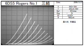
6DS5 SPICE Models
You are welcome, here is another one...
Triode-Connected:
Pentode:
You are welcome, here is another one...
Triode-Connected:
Code:
*
* Generic triode model: 6DS5_T_AN
* Copyright 2003--2008 by Ayumi Nakabayashi, All rights reserved.
* Version 3.10, Generated on Fri Mar 27 11:19:24 2015
*                 Plate
*                 | Grid
*                 | | Cathode
*                 | | |
.SUBCKT 6DS5_T_AN A G K
BGG   GG   0 V=V(G,K)+0.85903833
BM1   M1   0 V=(0.055442352*(URAMP(V(A,K))+1e-10))**-1.3320306
BM2   M2   0 V=(0.5296553*(URAMP(V(GG)+URAMP(V(A,K))/8.4834912)+1e-10))**2.8320306
BP    P    0 V=0.0027151857*(URAMP(V(GG)+URAMP(V(A,K))/16.017004)+1e-10)**1.5
BIK   IK   0 V=U(V(GG))*V(P)+(1-U(V(GG)))*0.002317914*V(M1)*V(M2)
BIG   IG   0 V=0.0013575929*URAMP(V(G,K))**1.5*(URAMP(V(G,K))/(URAMP(V(A,K))+URAMP(V(G,K)))*1.2+0.4)
BIAK  A    K I=URAMP(V(IK,IG)-URAMP(V(IK,IG)-(0.0016157998*URAMP(V(A,K))**1.5)))+1e-10*V(A,K)
BIGK  G    K I=V(IG)
* CAPS
CGA   G    A 0.19p
CGK   G    K 9.5p
CAK   A    K 6.3p
.ENDS
Pentode:
Code:
*
* Generic pentode model: 6DS5_AN
* Copyright 2003--2008 by Ayumi Nakabayashi, All rights reserved.
* Version 3.10, Generated on Fri Mar 27 11:31:14 2015
*               Plate
*               | Screen Grid
*               | |  Control Grid
*               | |  |  Cathode
*               | |  |  |
.SUBCKT 6DS5_AN A G2 G1 K
BGG   GG   0 V=V(G1,K)+0.85904403
BM1   M1   0 V=(0.055442514*(URAMP(V(G2,K))+1e-10))**-1.3320359
BM2   M2   0 V=(0.5296543*(URAMP(V(GG)+URAMP(V(G2,K))/8.4834842)))**2.8320359
BP    P    0 V=0.0020635445*(URAMP(V(GG)+URAMP(V(G2,K))/16.017021))**1.5
BIK   IK   0 V=U(V(GG))*V(P)+(1-U(V(GG)))*0.0017616257*V(M1)*V(M2)
BIG   IG   0 V=0.0010317722*URAMP(V(G1,K))**1.5*(URAMP(V(G1,K))/(URAMP(V(A,K))+URAMP(V(G1,K)))*1.2+0.4)
BIK2  IK2  0 V=V(IK,IG)*(1-0.4*(EXP(-URAMP(V(A,K))/URAMP(V(G2,K))*15)-EXP(-15)))
BIG2T IG2T 0 V=V(IK2)*(0.930724091*(1-URAMP(V(A,K))/(URAMP(V(A,K))+10))**1.5+0.069275909)
BIK3  IK3  0 V=V(IK2)*(URAMP(V(A,K))+1060)/(URAMP(V(G2,K))+1060)
BIK4  IK4  0 V=V(IK3)-URAMP(V(IK3)-(0.0012280096*(URAMP(V(A,K))+URAMP(URAMP(V(G2,K))-URAMP(V(A,K))))**1.5))
BIP   IP   0 V=URAMP(V(IK4,IG2T)-URAMP(V(IK4,IG2T)-(0.0012280096*URAMP(V(A,K))**1.5)))
BIAK  A    K I=V(IP)+1e-10*V(A,K)
BIG2  G2   K I=URAMP(V(IK4,IP))
BIGK  G1   K I=V(IG)
* CAPS
CGA   G1  A  0.19p
CGK   G1  K  5.7p
C12   G1  G2 3.8p
CAK   A   K  6.3p
.ENDSHi jazbo8,
Thank you very much! The 6DS5 LTSpice model worked great! 🙂
Thanks again for your helps!
Thank you very much! The 6DS5 LTSpice model worked great! 🙂
Thanks again for your helps!
Hi jazbo8
Any chance of the Ayumi spice models for a couple of the Emission Labs valves I'm looking at building an SE amp from? I spent all of last night trying to figure out how to work them out for myself but to no avail.
Specifically:
1) The 520B (output tube): 520B-V2 and 520B-V3 Data sheet Emission Labs.
2) The EML 20B (driver) : EML-20A-20B-30A Data sheet. By Emission Labs.
http://www.emissionlabs.com/datasheets/SOFIA/EML20B-Curves.gif
Thanks very much in advance.
- Home
- Amplifiers
- Tubes / Valves
- Vacuum Tube SPICE Models