But you just have resistors between primary and center tap. the real model of a transformer is
What about those inductances and core losses?
Thanks
What about those inductances and core losses?
Thanks
Please look more carefully at the code... hint, what are the L's and the K's doing?But you just have resistors between primary and center tap. the real model of a transformer is... What about those inductances and core losses?
Thanks
What primary inductance do you usually have with simulations ?
The permeability of the transformer core is increased when the voltage accross the primary is increased. This change can be some 4..5 times when the voltage varies from 5 V to 200 V.
The permeability of the transformer core is increased when the voltage accross the primary is increased. This change can be some 4..5 times when the voltage varies from 5 V to 200 V.
When available, the L's are based on the data provided by the manufacturers, else, they are based on the measurements e.g., as shown by Yves M. and others.What primary inductance do you usually have with simulations ?
Thanks, it is indeed better, from 0V to -10V could be better though, I will try to re-do Ayumi's GU-50 model when I get a chance, not sure which datasheet JA2DHC used for his version, but it certainly does not match up well with the LS50 data.LS50 curves from post 617 🙂
Curves by Matejs model (from -5 to -25 V) looks good.
Do you know which datasheet the GU-50 model was based on? I am not able to match it to any of the GU/LS/RY-50 datasheets I have seen...😕
For example, here is one vs. the Telefunken LS50:
No i just downloaded a model that i found.
Last edited:
No worries, in any case, matejsirk posted a better model above. You can also dis-regard the GU-50 models from JA2DHC and the one I posted earlier.
Yes i alreddy a'm using that one
now for somthing else i tried to find the model voor the E180F ( 6J9P ) if it is posted on what page can i find it
now for somthing else i tried to find the model voor the E180F ( 6J9P ) if it is posted on what page can i find it
E180F SPICE Model
Here you go:
Yes i alreddy a'm using that one
now for somthing else i tried to find the model voor the E180F ( 6J9P ) if it is posted on what page can i find it
Here you go:
Code:
*
* Generic pentode model: E180F_AN
* Copyright 2003--2008 by Ayumi Nakabayashi, All rights reserved.
* Version 3.10, Generated on Fri Dec 05 13:13:13 2014
*                Plate
*                | Screen Grid
*                | |  Control Grid
*                | |  |  Cathode
*                | |  |  |
.SUBCKT E180F_AN A G2 G1 K
BGG   GG   0 V=V(G1,K)+-0.47741291
BM1   M1   0 V=(0.011310585*(URAMP(V(G2,K))+1e-10))**-1.1037743
BM2   M2   0 V=(0.57608681*(URAMP(V(GG)+URAMP(V(G2,K))/37.479334)))**2.6037743
BP    P    0 V=0.021640679*(URAMP(V(GG)+URAMP(V(G2,K))/65.058484))**1.5
BIK   IK   0 V=U(V(GG))*V(P)+(1-U(V(GG)))*0.015425385*V(M1)*V(M2)
BIG   IG   0 V=0.010820339*URAMP(V(G1,K))**1.5*(URAMP(V(G1,K))/(URAMP(V(A,K))+URAMP(V(G1,K)))*1.2+0.4)
BIK2  IK2  0 V=V(IK,IG)*(1-0.4*(EXP(-URAMP(V(A,K))/URAMP(V(G2,K))*15)-EXP(-15)))
BIG2T IG2T 0 V=V(IK2)*(0.79503106*(1-URAMP(V(A,K))/(URAMP(V(A,K))+10))**1.5+0.20496894)
BIK3  IK3  0 V=V(IK2)*(URAMP(V(A,K))+2280)/(URAMP(V(G2,K))+2280)
BIK4  IK4  0 V=V(IK3)-URAMP(V(IK3)-(0.011321203*(URAMP(V(A,K))+URAMP(URAMP(V(G2,K))-URAMP(V(A,K))))**1.5))
BIP   IP   0 V=URAMP(V(IK4,IG2T)-URAMP(V(IK4,IG2T)-(0.011321203*URAMP(V(A,K))**1.5)))
BIAK  A    K I=V(IP)+1e-10*V(A,K)
BIG2  G2   K I=URAMP(V(IK4,IP))
BIGK  G1   K I=V(IG)
* CAPS
CGA   G1  A  0.03p
CGK   G1  K  0.1p
C12   G1  G2 0p
CAK   A   K  0.1p
.ENDSYes i alreddy a'm using that one
now for somthing else i tried to find the model voor the E180F ( 6J9P ) if it is posted on what page can i find it
I have this one:
.SUBCKT E180F 1 4 2 3
+ PARAMS: MU= 56.00 EX= 1.350 KG1= 250.0 KP=6709.19 KC= 850
+ KVB= 7.9 VCT= 0.00 RGI=2k
+ CCG=8.5P CPG1=0.03P CCP=3P
RE1 7 0 1G
RE2 8 3 1G
E1 7 0 VALUE= ; E1 BREAKS UP LONG EQUATION FOR G1.
+{V(4,3)/KP*LOG(1+EXP((1/MU+V(2,3)/V(4,3))*KP))}
G1 1 3 VALUE={(PWR(V(7),EX)+PWRS(V(7),EX))/KG1*ATAN(V(1,3)/KVB)}
G2 8 3 VALUE={(PWR(V(7),EX)+PWRS(V(7),EX))/KC*(2.5708-ATAN(V(1,3)/KVB))}
E2 8 4 VALUE={0}
RCP 1 3 1G ; FOR CONVERGENCE
C1 2 3 {CCG} ; CATHODE-GRID 1
C2 1 2 {CPG1} ; GRID 1-PLATE
C3 1 3 {CCP} ; CATHODE-PLATE
R1 2 5 {RGI} ; FOR GRID CURRENT
D3 5 3 DX ; FOR GRID CURRENT
.MODEL DX D(IS=1N RS=1 CJO=10PF TT=1N)
.ENDS
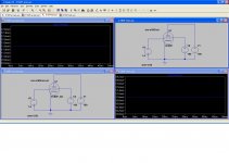
Please check which one is better.
I found that the e180f_an is better see for yourself
Attachments

Last edited:
When available, the L's are based on the data provided by the manufacturers, else, they are based on the measurements e.g., as shown by Yves M. and others.
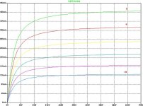
Some manufacturers provide the primary inductance (obviously) based on on the "old" test procedure (5 Vrms/50Hz), some, like Edcor does not provide this info at all and some. like Amplimo gives the "maximum" value, whic refers to some 200 Vrms tets voltage.
The primary inductance value can vary from, say 25 H to 125 H depending on the test voltage.
As an example, I measured the Lp of Indel TGL40/001, which is a OPT I have used a lot.
The results with different test voltage (50 Hz):
1Vrms......6.8 H
5 -"- .......9.4 H
50 -"-..... 23 H
100 -"- ....32 H
200 Vrms...43 H
When simulating, the results with 6.8 H and 43 H are very, very different.
So, this is not that simple matter.
Understood, the user needs to determine the correct parameters to use for the model, garbage in = garbage out, etc. 😉So, this is not that simple matter.
I suppose that "KALL LP1 LP2 LS1 .9999875" states that coupling factor between all inductors is .9999875, right? But there are not an ferromagnetic core neither hysteresis losses.
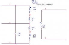
That's correct, please do a search on this forum (or Google) on OPT modeling if you are interested in building more detailed models than the one provided.
- Home
- Amplifiers
- Tubes / Valves
- Vacuum Tube SPICE Models