I look forward to test that model.
I have a 100 pcs. carton of 6N1P-EV.
Hi artosalo
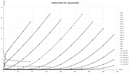
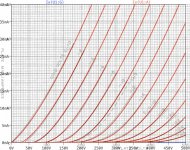
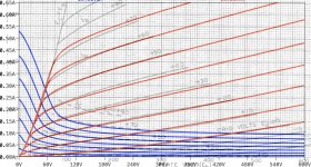
My 5 6N1Ps have done their 100h burn-in, and I startet with the measurements. The first triode went well trough my measurement process, see picture.
But with the next, things went wrong - no idea what happened!
So I first have to find the root cause, and fix my iTracer. 😡
I'll be busy the next days, so I cannot say when I can present a 6N1P model.
Sorry! 🙁
regards, Adrian
Attachments
Here is 300B based on WE datasheet:
Code:
**** 300B_WE ** Advanced Grid Current **********************************
* Created on 11/16/2020 22:10 using paint_kit.jar 3.1
* [URL="http://www.dmitrynizh.com/tubeparams_image.htm"]www.dmitrynizh.com/tubeparams_image.htm[/URL]
* Plate Curves image file: 300b-we.png
* Data source link:
*----------------------------------------------------------------------------------
.SUBCKT 300B_WE 1 2 3 ; Plate Grid Cathode
+ PARAMS: CCG=8.5P  CGP=15P CCP=4.1P
+ MU=3.978 KG1=1796.95 KP=44.97 KVB=39.73 VCT=-0.1505 EX=1.464
+ VGOFF=-1.5 IGA=5.176E-5 IGB=2.806 IGC=0.1501 IGEX=0.8008
* Vp_MAX=700 Ip_MAX=360 Vg_step=20 Vg_start=40 Vg_count=11
* Rp=4000 Vg_ac=55 P_max=36 Vg_qui=-48 Vp_qui=300
* X_MIN=45 Y_MIN=21 X_SIZE=772 Y_SIZE=503 FSZ_X=1296 FSZ_Y=736 XYGrid=true
* showLoadLine=n showIp=y isDHT=n isPP=n isAsymPP=n showDissipLimit=y
* showIg1=y gridLevel2=y isInputSnapped=n
* XYProjections=n harmonicPlot=n dissipPlot=n
*----------------------------------------------------------------------------------
E1 7 0 VALUE={V(1,3)/KP*LOG(1+EXP(KP*(1/MU+(VCT+V(2,3))/SQRT(KVB+V(1,3)*V(1,3)))))}
RE1 7 0 1G  ; TO AVOID FLOATING NODES
G1 1 3 VALUE={(PWR(V(7),EX)+PWRS(V(7),EX))/KG1}
RCP 1 3 1G   ; TO AVOID FLOATING NODES
C1 2 3 {CCG} ; CATHODE-GRID
C2 2 1 {CGP} ; GRID=PLATE
C3 1 3 {CCP} ; CATHODE-PLATE
RE2 2 0 1G
EGC 8 0 VALUE={V(2,3)-VGOFF} ; POSITIVE GRID THRESHOLD
GG 2 3 VALUE={(IGA+IGB/(IGC+V(1,3)))*(MU/KG1)*(PWR(V(8),IGEX)+PWRS(V(8),IGEX))}
.ENDS
*$
Attachments
Hello, I'm new to LTSpice on Mac OSX and am trying to figure out how to import these subcircuits (the Ayumi folder of .inc files on the first page).
I've spent a fair amount of time googling and watching tutorials, and I must be missing something obvious because I can't seem to do it.
If anyone has any easy tips I'd appreciate it!
I've spent a fair amount of time googling and watching tutorials, and I must be missing something obvious because I can't seem to do it.
If anyone has any easy tips I'd appreciate it!
brad347 & Datun Walnut the easiest way is to copy the subcircuits and paste using Spice Directive ( .op ) on the page of your schematic ....all the best
Before you assume you're doing it wrong, make sure in the .inc file all instances of ^ are changed to ** . (PSpice uses ^ while LTspice uses ** )
I organize my models so I can choose them from the list that appears when I click the Component icon in LTspice IV. (The following is for LTspiceIV running in Windows only. Hopefully these steps can translate to LTspiceXVI...)
I. Under ...\LTC\LTspiceIV\lib\sym\
Create a new subdirectory \Tubes\ (...\LTC\LTspiceIV\lib\sym\Tubes\)
Under that create new subdirectories
...\Tubes\Triodes\
...\Tubes\Pentodes\
...\Tubes\Tetrodes\
...\Tubes\Diodes\
and so on.
Now in your LTspice schematic window, when you click the Component icon from the toolbar, the menu will show [Tubes] as a section. Double-click on [Tubes] and you'll see the subsections [Triodes], [Pentodes], [Tetrodes], [Diodes].
In Notepad, open \LTC\LTspice\lib\sub\12AX7_AN.inc .
- Notice the text that comes immediately after .SUBCKT in that file.
In my 12AX7_AN.inc file it says "12AX7_AN" there.
Remember that. It will be important to know what this is, later.
II. Now it's time to make a 12AX7 triode symbol that works with the appropriate Ayumi .inc file.
1) Here are the contents of a generic triode symbol Triode.asy.
Copy and paste that into Notepad (or any plain text editor of your choosing). Save that file as \LTC\LTspiceIV\lib\sym\Tubes\Triodes\Triode.asy
(If you don't know how to do that, then it's time for some basic 'how to use DOS and Windows', which is beyond the scope of this discussion. Be careful not to save the file as Triode.asy.txt!!)
2) Make a copy of that Triode.asy file and name it
\LTC\LTspiceIV\lib\sym\Tubes\Triodes\12AX7_AN.asy
3) Let's say the 12AX7 model symbol you want to make is based on 12AX7_AN.inc.
Going back to the new symbol, find the three lines
Change those three lines (and only those three lines) to the following four lines:
SYMATTR Value tells LTspice what the name of the symbol will be when it appears in an LTspice schematic.
(Notice how I didn't use "12AX7_AN" here. That's because I want the symbol to display as "12AX7" in my schematic. You could call it "12AX7_AN" if you have multiple 12AX7 models and you want to show which one you used. Or you might want to have your schematic show "ECC83" if you're more comfortable using the European name for the 12AX7 type.)
SYMATTR SpiceModel tells LTspice what file to look for in the \LTC\LTspiceIV\lib\sub\ directory.
(It has to be the exact name of the file in the ...\sub\ directory, which in this case is "12AX7_AN.inc".)
SYMATTR Value2 tells LTspice what exact text to look for immediately following the text .SUBCKT.
Those all need to match up *exactly* (case sensitive, no added spaces or other characters). In our 12AX7_AN.inc file, the .SUBCKT line looks like this:
The text "12AX7_AN" appears immediately after the text ".SUBCKT". That's what the SYMATTR Value2 statement points to in the .inc file.
4) Then comes the order of pins and their names.
In the generic Triode.asy file, the PinName and SpiceOrder statements are as below:
In the 12AX7_AN.inc (not the .asy) file, the pin names and pin order comes immediately after the SYMATTR Value2 variable in the .SUBCKT line:
As you can see, the pin names are A G and K, and the pin order is 1=A, 2=G and 3=K (A for Anode, G for Grid, K for Cathode)
In this case the Ayumi .inc file contents match what's in the Triode.asy file. You don't have to change anything (isn't that convenient?). The .inc or .sub files from other makers of SPICE models may have a different SpiceOrder (order of pins) or different PinName assignments. You will need to edit your .asy files to match the .inc or the .sub files. (Don't try to edit the .inc or .sub files. You may break them!)
5) Save your new .asy file as
\LTC\LTspiceIV\lib\sym\Tubes\Triodes\12AX7_AN.asy
Now the next time you open LTspice and click on the Component icon from the toolbar, you'll see a section [Tubes]. Double-click that and you'll see a section [Triodes]. Double-click that and you'll see 12AX7_AN waiting for you to select.
I hope that helps (and sorry for any mistakes I may have made.)
--
PS - Here is a generic pentode symbol. You'll need to modify it as necessary. Save it as Pentode.asy in the Pentodes directory folder under Tubes, i.e.
\LTC\LTspiceIV\lib\sym\Tubes\Pentodes\Pentode.asy
--
PPS - I believe cogsncogs posted a way to use the generic Triode.asy and Pentode.asy models to create a symbol with a dropdown list you can pick and choose from. I have not experimented with that. I know some people prefer choosing their models that way.
--
I organize my models so I can choose them from the list that appears when I click the Component icon in LTspice IV. (The following is for LTspiceIV running in Windows only. Hopefully these steps can translate to LTspiceXVI...)
I. Under ...\LTC\LTspiceIV\lib\sym\
Create a new subdirectory \Tubes\ (...\LTC\LTspiceIV\lib\sym\Tubes\)
Under that create new subdirectories
...\Tubes\Triodes\
...\Tubes\Pentodes\
...\Tubes\Tetrodes\
...\Tubes\Diodes\
and so on.
Now in your LTspice schematic window, when you click the Component icon from the toolbar, the menu will show [Tubes] as a section. Double-click on [Tubes] and you'll see the subsections [Triodes], [Pentodes], [Tetrodes], [Diodes].
In Notepad, open \LTC\LTspice\lib\sub\12AX7_AN.inc .
- Notice the text that comes immediately after .SUBCKT in that file.
In my 12AX7_AN.inc file it says "12AX7_AN" there.
Code:
*
* Generic triode model: 12AX7_AN
* Copyright 2003--2008 by Ayumi Nakabayashi, All rights reserved.
* Version 3.10, Generated on Sat Mar  8 22:41:09 2008
*                Plate
*                | Grid
*                | | Cathode
*                | | |
.SUBCKT 12AX7_AN A G K
Remember that. It will be important to know what this is, later.
II. Now it's time to make a 12AX7 triode symbol that works with the appropriate Ayumi .inc file.
1) Here are the contents of a generic triode symbol Triode.asy.
Code:
Version 4
SymbolType CELL
LINE Normal -48 0 -28 0
LINE Normal -20 0 -12 0
LINE Normal -4 0 4 0
LINE Normal 12 0 20 0
LINE Normal 28 0 36 0
LINE Normal 0 -48 0 -16
LINE Normal -20 -16 20 -16
LINE Normal -20 -12 20 -12
LINE Normal -20 -16 -20 -12
LINE Normal 20 -16 20 -12
LINE Normal -24 12 24 12
LINE Normal -32 48 -32 20
LINE Normal -24 12 -32 20
LINE Normal 24 12 32 20
LINE Normal -28 16 28 16
CIRCLE Normal -48 -48 48 48
WINDOW 0 8 -64 Left 0
WINDOW 3 -24 64 Left 0
SYMATTR Value Triode
SYMATTR Prefix X
SYMATTR Description This symbol is for use with a subcircuit macromodel that you supply.
PIN 0 -48 NONE 0
PINATTR PinName Plate
PINATTR SpiceOrder 1
PIN -48 0 NONE 0
PINATTR PinName Grid
PINATTR SpiceOrder 2
PIN -32 48 NONE 0
PINATTR PinName Cathode
PINATTR SpiceOrder 3
Copy and paste that into Notepad (or any plain text editor of your choosing). Save that file as \LTC\LTspiceIV\lib\sym\Tubes\Triodes\Triode.asy
(If you don't know how to do that, then it's time for some basic 'how to use DOS and Windows', which is beyond the scope of this discussion. Be careful not to save the file as Triode.asy.txt!!)
2) Make a copy of that Triode.asy file and name it
\LTC\LTspiceIV\lib\sym\Tubes\Triodes\12AX7_AN.asy
3) Let's say the 12AX7 model symbol you want to make is based on 12AX7_AN.inc.
Going back to the new symbol, find the three lines
Code:
SYMATTR Value Triode
SYMATTR Prefix X
SYMATTR Description This symbol is for use with a subcircuit macromodel that you supply.
Change those three lines (and only those three lines) to the following four lines:
Code:
SYMATTR Value 12AX7
SYMATTR Prefix X
SYMATTR SpiceModel 12AX7_AN.inc
SYMATTR Value2 12AX7_AN
SYMATTR Value tells LTspice what the name of the symbol will be when it appears in an LTspice schematic.
(Notice how I didn't use "12AX7_AN" here. That's because I want the symbol to display as "12AX7" in my schematic. You could call it "12AX7_AN" if you have multiple 12AX7 models and you want to show which one you used. Or you might want to have your schematic show "ECC83" if you're more comfortable using the European name for the 12AX7 type.)
SYMATTR SpiceModel tells LTspice what file to look for in the \LTC\LTspiceIV\lib\sub\ directory.
(It has to be the exact name of the file in the ...\sub\ directory, which in this case is "12AX7_AN.inc".)
SYMATTR Value2 tells LTspice what exact text to look for immediately following the text .SUBCKT.
Those all need to match up *exactly* (case sensitive, no added spaces or other characters). In our 12AX7_AN.inc file, the .SUBCKT line looks like this:
Code:
.SUBCKT 12AX7_AN A G KThe text "12AX7_AN" appears immediately after the text ".SUBCKT". That's what the SYMATTR Value2 statement points to in the .inc file.
4) Then comes the order of pins and their names.
In the generic Triode.asy file, the PinName and SpiceOrder statements are as below:
Code:
PIN 0 -48 NONE 0
PINATTR PinName A
PINATTR SpiceOrder 1
PIN -48 0 NONE 0
PINATTR PinName G
PINATTR SpiceOrder 2
PIN -32 48 NONE 0
PINATTR PinName K
PINATTR SpiceOrder 3
In the 12AX7_AN.inc (not the .asy) file, the pin names and pin order comes immediately after the SYMATTR Value2 variable in the .SUBCKT line:
Code:
.SUBCKT 12AX7_AN A G KAs you can see, the pin names are A G and K, and the pin order is 1=A, 2=G and 3=K (A for Anode, G for Grid, K for Cathode)
In this case the Ayumi .inc file contents match what's in the Triode.asy file. You don't have to change anything (isn't that convenient?). The .inc or .sub files from other makers of SPICE models may have a different SpiceOrder (order of pins) or different PinName assignments. You will need to edit your .asy files to match the .inc or the .sub files. (Don't try to edit the .inc or .sub files. You may break them!)
5) Save your new .asy file as
\LTC\LTspiceIV\lib\sym\Tubes\Triodes\12AX7_AN.asy
Now the next time you open LTspice and click on the Component icon from the toolbar, you'll see a section [Tubes]. Double-click that and you'll see a section [Triodes]. Double-click that and you'll see 12AX7_AN waiting for you to select.
I hope that helps (and sorry for any mistakes I may have made.)
--
PS - Here is a generic pentode symbol. You'll need to modify it as necessary. Save it as Pentode.asy in the Pentodes directory folder under Tubes, i.e.
\LTC\LTspiceIV\lib\sym\Tubes\Pentodes\Pentode.asy
Code:
Version 4
SymbolType CELL
LINE Normal -48 -16 -48 16
LINE Normal 48 -16 48 16
LINE Normal 0 -64 0 -32
LINE Normal -20 -32 20 -32
LINE Normal -20 -28 20 -28
LINE Normal -20 -32 -20 -28
LINE Normal 20 -32 20 -28
LINE Normal 20 -16 12 -16
LINE Normal 4 -16 -4 -16
LINE Normal -12 -16 -20 -16
LINE Normal -28 -16 -48 -16
LINE Normal 48 0 28 0
LINE Normal 20 0 12 0
LINE Normal 4 0 -4 0
LINE Normal -12 0 -20 0
LINE Normal -48 16 -28 16
LINE Normal -20 16 -12 16
LINE Normal -4 16 4 16
LINE Normal 12 16 20 16
LINE Normal -24 28 24 28
LINE Normal -32 64 -32 36
LINE Normal -24 28 -32 36
LINE Normal 24 28 32 36
LINE Normal -28 32 28 32
ARC Normal -48 -64 48 32 48 -16 -48 -16
ARC Normal -48 -32 48 64 -48 16 48 16
WINDOW 0 8 -80 Left 0
WINDOW 3 -24 80 Left 0
SYMATTR Value Pentode
SYMATTR Prefix X
SYMATTR Description This symbol is for use with a subcircuit macromodel that you supply.
PIN -32 64 NONE 0
PINATTR PinName Cathode
PINATTR SpiceOrder 1
PIN -48 16 NONE 0
PINATTR PinName G1
PINATTR SpiceOrder 2
PIN 48 0 NONE 0
PINATTR PinName G2
PINATTR SpiceOrder 3
PIN -48 -16 NONE 0
PINATTR PinName G3
PINATTR SpiceOrder 4
PIN 0 -64 NONE 0
PINATTR PinName Anode
PINATTR SpiceOrder 5
--
PPS - I believe cogsncogs posted a way to use the generic Triode.asy and Pentode.asy models to create a symbol with a dropdown list you can pick and choose from. I have not experimented with that. I know some people prefer choosing their models that way.
--
Last edited:
Thanks for that - I'm getting a lot nearer now. I made one for an ECC88 and when I try to run a simulation, I get: 'Unknown subcircuit called in xu1 p001 n003 n004 ecc88 a g k" all in lower case even tho mine is in upper.
Thanks for that - I'm getting a lot nearer now. I made one for an ECC88 and when I try to run a simulation, I get: 'Unknown subcircuit called in xu1 p001 n003 n004 ecc88 a g k" all in lower case even tho mine is in upper.
Upper case vs lower case should not matter.
If you can post your .asy file and your .inc file, I can take a look.
I'm not having the best luck, either. I'm in Mac OSX, but most of the above was fairly easily portable to my environment.
I made a 12AX7 in the library file as per instructions above. When I go to add component to my schematic, I see my new "tubes" folder, and I see "12AX7.asy" there. But when I select it nothing happens.
I'll try again another day
I made a 12AX7 in the library file as per instructions above. When I go to add component to my schematic, I see my new "tubes" folder, and I see "12AX7.asy" there. But when I select it nothing happens.
I'll try again another day
Dear all,
may I ask you a model fr this tube?
https://frank.pocnet.net/sheets/095/6/6P13P.pdf
Thank you in advance,
Kind Regards
may I ask you a model fr this tube?
https://frank.pocnet.net/sheets/095/6/6P13P.pdf
Thank you in advance,
Kind Regards
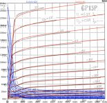
Hi zintolo
Freshly backed:
Enjoy!
cheers, Adrian
Freshly backed:
Code:
*6P13P LTspice model based on the generic tetrode/pentode model from Adrian Immler, version i4, Nov 2020
*Be aware that the iG1 model is just guessed due to lack of iG1 data!!
*A version log is at the end of this file
*Params fitted to chinese datasheet by Adrian Immler, Nov 2020
*This model is an enhancement of Adrians generic triode model to achieve tetrode/pentode behaviour.
*Hence, it is also suitable when the tetrode/pentode is "triode connected".
*Convenient for tetrodes, power beam tetrodes and g3-grounded pentodes.
*Copes secondary emission effect!
*
*             version i4
*             | p=preliminary due to lack of iG1 data
*             | | plate (in this model, "anode" means the internal virtual triode anode)
*             | | | grid2
*             | | | |  grid1
*             | | | |  |  cathode
*             | | | |  |  |
.subckt 6P13P.i4p P G2 G1 K
.params
*Parameters for the space charge current @ Vg <= 0
+ mu1 = 9       ;Main factor for voltage gain @ constant Ia in triode mode
+ ks = 325      ;Permeance factor. Has to be readjusted if xs is changed
+ Vg0 = 0.35    ;Offsets the Ia-traces on the Va axis. Electrode material's contact potential
+ kp = 37       ;Mimics the island effect
+ xs = 1.5      ;Determines the curve of the Ia traces. Typically between 1.2 and 1.8
*
*Parameters for an optional space charge current reduction @ Vg > 0
+ kIsr = 0.0    ;Va independable Is reduction, a function of Vg1
+ Rg1i = 10     ;Internal grid1 resistor which causes an extra Is drop when Va approaches zero.
*
*Parameters for assigning the space charge current to Ia and Ig @ Vg > 0 and small Va
+ kB1 = 0.3     ;Describes how fast Ia_virtual drops to zero when Va_virtual approaches zero.
+ radl = 275    ;Differential resistance for the Ia emission limit @ very small Va and Vg > 0
+ tsh = 12      ;Ia transmission sharpness from 1th to 2nd Ia area. Keep between 3 and 20. Start with 20.
+ xl = 1.3      ;Exponent for the emission limit
+ Vctl = 0 f=0  ;Offsets the Ia emission limit trace on the Va axis. f=related Vg1 koeff.
*
*Parameters of the grid-cathode vacuum diode
+ kg1 = 3k      ;estimated value!!
+ Vctg1 = 0.55  ;estimated value!!
+ xg1 = 1.5     ;Determines the curve of the Ig slope versus (positive) Vg and Va >> 0
+ VT = 0.1      ;Log(Ig) slope @ Vg<0. VT=k/q*Tk (cathodes absolute temp, typically 1150K)
*
*Parameters for the caps
+ cg1p  = 0p5   ;according datasheet
+ cg1All= 6p5   ;according datasheet
+ CpAll = 18p5  ;according datasheet
+ Cpk   = 1p    ;guessed value, not mentioned in datasheet
*
*Parameters to enhance the triode model to a pentode model
+ mu2 = 44      ;1/mu2 is the fraction of Vp which together with Vg2i builds the virtual Triode-Anode Voltage
+ kB2 = 0.2     ;Describes how fast Ip drops to zero when Vp approaches zero.
+ Rg2i = 10     ;Internal grid2 resistor. Causes an Is reduction when Ig2 increases while Vp drops
+ fr2 = 0.07    ;determines the residual ig2 fraction @ high Va values
+ ftfr2 = 0     ;if fr2 showes a Vg2 dependancy, this can be considered with this parameter
*
*Parameters to mimic the secondary emission (inspired from Derk Reefmans approach)
+ co = 1.5      ;decribes the crossover region (Ise drop when Va increase). between 0 and 9
+ Vse=55   a=0  ;Va where the sec. emission is strongest. a=related Vg1 coefficient
+ Ise0=0m3 b=0m4;sec. emission peak current @ Vg=0. b=related Vg1 coefficient
+ Vg2ref = 150  ;Vg2 where the following coeffficients has no influence to the emission effect:
+ c = 0         ;Vg2 coefficient of a
+ d = 0         ;exp Vg2 coefficient of Ise0
+ e = 0         ;Vg2 coeff. of b
*
*Calculated parameters
+ kl = pow(1/(radl*xl*Ild**(1-1/xl)),-xl) ;Reduces the xl influence to the Ia slope @ small Va
+ Ild = sqrt(radl)*1m ;Current where the limited anode a.c. resistance is set according to radl.
*
*Space charge current model
Bggi GG1i 0 V=v(G1i,K)+Vg0 - v(G1,K)*(1-1/(1+kIsr*max(0,v(G1,K)))) ;Effective internal grid voltage.
Bahc Ahc 0 V=uramp(v(P,K)/mu2+v(G2i,K)) ;voltage of the virtual triode anode, hard cut to zero
Bst St 0 V=max(v(GG1i)+v(Ahc)/(mu1), v(Ahc)/kp*ln(1+exp(kp*(1/mu1+v(GG1i)/(1+v(Ahc))))));Steering volt.
Bs Ai K I=1/ks*pow(v(St),xs) ;Langmuir-Childs law for the space charge current Is
*
*Anode current limit @ small Va
.func smin(x,y,n) {pow(pow(x + 1f, -n)+pow(y+1f, -n), -1/n)} ;Min-function with smooth trans.
Ra A Ai 1
Bpl G2i P I=i(Rp) - smin(1/kl*pow(v(P,K)+min(0,Vctl+f*v(G1,K)),xl),i(Rp),tsh);Ip emission limit
*
*Grid model
Rg1i G1 G1i {Rg1i} ;Internal grid resistor for "Ia-reduction" @ Vg > 0
.func Ivd(Vvd, kvd, xvd, VTvd) {1/kvd*pow(VTvd*xvd*ln(1+exp(Vvd/VTvd/xvd)),xvd)} ;Vacuum diode function
Bg1vd G1 K I=Ivd(v(G1,K)+Vctg1-1m*sqrt(v(Ahc)), kg1, xg1, VT) ;Grid-cathode vacuum diode
Bg1r G1i Ai I=ivd(v(GG1i),ks, xs, 0.8*VT)/(1+kB1*v(Ahc));Is reflection to grid when Va appr. zero
Bs0 Ai K I=ivd(v(GG1i),ks, xs, 0.8*VT) - 1/ks*pow(v(GG1i),xs) ;Compensates neg Ia
*@ small Va and Vg near zero
*
*additional model parts necessary for a pentode
Rg2i G2 G2i {Rg2i}
Rp P A 1
Bg2r G2i A I=i(Ra)*((1-frg2())/(1+kB2*max(0,v(P,K))) ) ; Va dependable ig2 part, reflected from the plate
Bg2f G2  A I=i(Ra)*frg2() ; Va independable ig2 part. Not to lead this current over Rg2i improves convergence
.func frg2() {fr2*exp(ftfr2*(v(G2,K)-250))}
*
*model for secondary emission effect
*nomalizing function nf(sh) ensures that the peak of y=x*(1-tanh(sh(x-1)) is always at x=1 while sh=0..9
.func nf(z) {609m/z + 293m + 107m*z - 5.71m*z*z}
.func sh() {pow(co,2)} ;results in a more linear control of the cross over region with the param co
Bsee G2 P I=min(Ise()*nf(sh())*xf()*(1-tanh(sh()*(nf(sh())*xf()-1))) / (nf(sh())*(1-tanh(sh()*(nf(sh())-1)))),i(Rp)-i(Bpl))
.func Ise() {smin(uramp(Isef() - bf()*v(G1,K)),0.98*i(Rp),2)} ;avoides neg. Iplate caused by strong sec. em.
.func xf() {v(P,K)/(1m+uramp(Vse-af()*v(G1,K)))}; moves the sec emission peak to the wanted voltage Vsep
.func af() {a + c*(v(G2,K)-Vg2ref)}
.func Isef()   {Ise0 * exp(d*(v(G2,K)-Vg2ref))}
.func bf()  {b + e*((v(G2,K)-Vg2ref))}
*
*Caps
C1 G1 P {cg1p}
C2 G1 K {(cg1All-cg1p)/2} ;As this model does not consider the ambient as further electrodes for parasitic caps,
;best way is to assume this " g1 to all" cap as it would be half to cathode and half to g2 (after substraction of cg1p).
C3 G1 G2 {(cg1All-cg1p)/2}
C4 P K {cpk}
C5 P G2 {cpAll-cpk-cg1p}
.end
*
*Version log
*i1 :Initial version
*i2 :Pin order changed to the more common order "P G2 G1 K" (Thanks to Markus Gyger for his tip)
*i3 :residual ig2 @ large Va introduced; 2nd emission effect introduced;
;Va indep. grid current parts no longer lead over internal grid resistors for better convergence
*i4 :to improve convegence, the Ia reduction @ pos Vg is no longer done by Rg1i. Instead, kIsr introduced
;Furthermore, ks and Vg0 are set directly, as rad and Vct turned out to be usefull for triodes only
*i4f :Major bug fixed. Tube works now also when Cathode not grounded (for cathode follower and the like)
Enjoy!
cheers, Adrian
Attachments
Here is trial model, will update if any issue:
Code:* [URL="http://www.dmitrynizh.com/tubeparams_image.htm"]www.dmitrynizh.com/tubeparams_image.htm[/URL] * Plate Curves image file: E130L.png * Data source link: <plate curves URL> *---------------------------------------------------------------------------------- .SUBCKT E130L P G2 G K ; LTSpice tetrode.asy pinout * .SUBCKT E130L P G K G2 ; Koren Pentode Pspice pinout + PARAMS: MU=8.385 KG1=297113.95 KP=53.7 KVB=427.08 VCT=14.24 EX=3.231 KG2=564711.87 KNEE=865.42 KVC=1.948 + KLAM=3.281E-10 KLAMG=7.089E-4 KD=2136.62 KC=1.346E30 KR1=3.254E-5 KR2=7.823 KVBG=0.000983 KB1=8 KB2=7.04 KB3=2.02 KB4=0.195 KVBGI=0.05472 KNK=-0.03236 KNG=0.006438 KNPL=0.02578 KNSL=0.07314 KNPR=106 KNSR=44.14 + CCG=35P CGP=2P CCP=17P VGOFF=-0.6 IGA=0.001 IGB=0.3 IGC=8 IGEX=2 * Vp_MAX=300 Ip_MAX=1000 Vg_step=2 Vg_start=0 Vg_count=16 * X_MIN=81 Y_MIN=37 X_SIZE=674 Y_SIZE=560 FSZ_X=1296 FSZ_Y=736 XYGrid=false * Rp=1400 Vg_ac=20 P_max=27.5 Vg_qui=-15 Vp_qui=300 * showLoadLine=n showIp=y isDHP=n isPP=n isAsymPP=n isUL=n showDissipLimit=y * showIg1=y isInputSnapped=y addLocalNFB=n * XYProjections=n harmonicPlot=y dissipPlot=n * UL=0.43 EG2=150 gridLevel2=y addKink=y isTanhKnee=n advSigmoid=y *---------------------------------------------------------------------------------- RE1 7 0 1G ; DUMMY SO NODE 7 HAS 2 CONNECTIONS E1 7 0 VALUE= ; E1 BREAKS UP LONG EQUATION FOR G1. +{V(G2,K)/KP*LOG(1+EXP((1/MU+(VCT+V(G,K))/SQRT(KVB+V(G2,K)*V(G2,K)))*KP))} RE2 6 0 1G ; DUMMY SO NODE 6 HAS 2 CONNECTIONS E2 6 0 VALUE={(PWR(V(7),EX)+PWRS(V(7),EX))} ; Kg1 times KIT current E4 8 0 VALUE={V(P,K)/KNEE/(KVBGI+V(6)*KVBG)} E5 81 0 VALUE={PWR(V(8),KB1)} E6 82 0 VALUE={PWR(V(8),KB2)} E7 83 0 VALUE={PWR(V(8),KB3)} E8 9 0 VALUE={PWR(1-EXP(-V(81)*(KC+KR1*V(82))/(KD+KR2*V(83))),KB4)*1.5708} RE4 8 0 1 RE5 81 0 1 RE6 82 0 1 RE7 83 0 1 RE8 9 0 1 RE21 21 0 1 E21 21 0 VALUE={V(6)/KG1*V(9)} ; Ip with knee but no slope and no kink RE22 22 0 1 ; E22: kink curr deviation for plate E22 22 0 VALUE={V(21)*LIMIT(KNK-V(G,K)*KNG,0,0.3)*(-ATAN((V(P,K)-KNPL)/KNSL)+ATAN((V(P,K)-KNPR)/KNSR))} G1 P K VALUE={V(21)*(1+KLAMG*V(P,K))+KLAM*V(P,K) + V(22)} G2 G2 K VALUE={V(6)/KG2*(KVC-V(9))/(1+KLAMG*V(P,K)) - V(22)} RCP P K 1G ; FOR CONVERGENCE C1 K G {CCG} ; CATHODE-GRID 1 C2 G P {CGP} ; GRID 1-PLATE C3 K P {CCP} ; CATHODE-PLATE RE23 G 0 1G GG G K VALUE={(IGA+IGB/(IGC+V(P,K)))*(MU/KG1)* +(PWR(V(G,K)-VGOFF,IGEX)+PWRS(V(G,K)-VGOFF,IGEX))} .ENDS *$
This is update E130L model with improved convergence and alignment on zero bias line:
Code:
**** E130L ******************************************
* Created on 11/23/2020 21:11 using paint_kip.jar
* [url=http://www.dmitrynizh.com/tubeparams_image.htm]Model Paint Tools: Trace Tube Parameters over Plate Curves, Interactively[/url]
* Plate Curves image file: E130L.png
* Data source link: <plate curves URL>
*----------------------------------------------------------------------------------
.SUBCKT E130L P G2 G K ; LTSpice tetrode.asy pinout
* .SUBCKT E130L P G K G2 ; Koren Pentode Pspice pinout
+ PARAMS: MU=8.383 KG1=92.03 KP=63.63 KVB=1658.88 VCT=-2.17 EX=1.126 KG2=153.72 KNEE=5440.17 KVC=1.74
+ KLAM=6.25E-9 KLAMG=4.5E-4  KD=1.102 KC=0.1408 KR1=5.289E-7 KR2=0.001063 KVBG=1.216E-4 KB1=5.592 KB2=0 KB3=2 KB4=0.2697 KVBGI=1.152E-4 KNK=-0.008432 KNG=0.02399 KNPL=0.4572 KNSL=46.15 KNPR=69.89 KNSR=77.47
+ CCG=3P CGP=1.4P CCP=1.9P VGOFF=-0.6 IGA=0.001 IGB=0.3 IGC=8 IGEX=2
* Vp_MAX=300 Ip_MAX=1000 Vg_step=4 Vg_start=0 Vg_count=11
* X_MIN=56 Y_MIN=21 X_SIZE=749 Y_SIZE=624 FSZ_X=1296 FSZ_Y=736 XYGrid=false
* Rp=1400 Vg_ac=20 P_max=27.5 Vg_qui=-20 Vp_qui=300
* showLoadLine=n showIp=y isDHP=n isPP=n isAsymPP=n isUL=n showDissipLimit=y
* showIg1=y isInputSnapped=y addLocalNFB=n
* XYProjections=n harmonicPlot=y dissipPlot=n
* UL=0.43 EG2=150 gridLevel2=y addKink=y isTanhKnee=n advSigmoid=y
*----------------------------------------------------------------------------------
RE1  7 0  1G    ; DUMMY SO NODE 7 HAS 2 CONNECTIONS
E1   7 0  VALUE=  ; E1 BREAKS UP LONG EQUATION FOR G1.
+{V(G2,K)/KP*LOG(1+EXP((1/MU+(VCT+V(G,K))/SQRT(KVB+V(G2,K)*V(G2,K)))*KP))}
RE2  6 0  1G    ; DUMMY SO NODE 6 HAS 2 CONNECTIONS
E2  6 0  VALUE={(PWR(V(7),EX)+PWRS(V(7),EX))} ; Kg1 times KIT current
E4   8 0  VALUE={V(P,K)/KNEE/(KVBGI+V(6)*KVBG)}
E5  81 0  VALUE={PWR(V(8),KB1)}
E6  82 0  VALUE={PWR(V(8),KB2)}
E7  83 0  VALUE={PWR(V(8),KB3)}
E8   9 0  VALUE={PWR(1-EXP(-V(81)*(KC+KR1*V(82))/(KD+KR2*V(83))),KB4)*1.5708}
RE4  8 0  1
RE5 81 0  1
RE6 82 0  1
RE7 83 0  1
RE8  9 0  1
RE21 21 0 1
E21  21 0 VALUE={V(6)/KG1*V(9)} ; Ip with knee but no slope and no kink
RE22 22 0 1 ; E22: kink curr deviation for plate
E22  22 0 VALUE={V(21)*LIMIT(KNK-V(G,K)*KNG,0,0.3)*(-ATAN((V(P,K)-KNPL)/KNSL)+ATAN((V(P,K)-KNPR)/KNSR))}
G1   P K  VALUE={V(21)*(1+KLAMG*V(P,K))+KLAM*V(P,K) + V(22)}
G2   G2 K  VALUE={V(6)/KG2*(KVC-V(9))/(1+KLAMG*V(P,K)) - V(22)}
RCP  P K  1G     ; FOR CONVERGENCE
C1   K G  {CCG}  ; CATHODE-GRID 1
C2   G P  {CGP}  ; GRID 1-PLATE
C3   K P  {CCP}  ; CATHODE-PLATE
RE23 G 0 1G
GG G K VALUE={(IGA+IGB/(IGC+V(P,K)))*(MU/KG1)*
+(PWR(V(G,K)-VGOFF,IGEX)+PWRS(V(G,K)-VGOFF,IGEX))}
.ENDS
*$
Attachments
Hi DIYspaceW
Here you go:
Enjoy!
cheers, Adrian
Here you go:
Code:
*2C22 LTspice model based on the generic triode model from Adrian Immler, version i4
*A version log is at the end of this file
*Params fitted to RCA datasheet by Adrian Immler, Nov. 2020
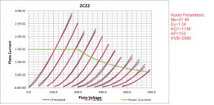
*The high fit quality is presented at adrianimmler.simplesite.com
*History's best of tube decribing art (plus some new ideas) is merged to this new approach.
*@ neg. Vg, Ia accuracy is similar to Koren or Ayumi models.
*@ small neg. Vg, the "Anlauf" current is considered.
*@ pos. Vg, Ig and Ia accuracy is on a unrivaled level.
*This offers new simulation possibilities like bias point setting with MOhm grid resistor,
*Audion radio circuits, low voltage amps, guitar distortion stages or pulsed stages.
* anode (plate)
* | grid
* | | cathode
* | | |
.subckt 2C22.RCi4 A G K
.params
*Parameters for the space charge current @ Vg <= 0
+ mu = 21.4 ;Determines the voltage gain @ constant Ia
+ rad = 5k4 ;Differential anode resistance, set @ Iad and Vg=0V
+ Vct = 1.2 ;Offsets the Ia-traces on the Va axis. Electrode material's contact potential
+ kp = 160 ;Mimics the island effect
+ xs = 1.4 ;Determines the curve of the Ia traces. Typically between 1.2 and 1.8
*
*Parameters for assigning the space charge current to Ia and Ig @ Vg > 0
+ kB = 0.055;Describes how fast Ia drops to zero when Va approaches zero.
+ radl = 280 ;Differential resistance for the Ia emission limit @ very small Va and Vg > 0
+ tsh = 10 ;Ia transmission sharpness from 1th to 2nd Ia area. Keep between 3 and 20. Start with 20.
+ xl = 1.3 ;Exponent for the emission limit
*
*Parameters of the grid-cathode vacuum diode
+ kvdg = 35 ;virtual vacuumdiode. Causes an Ia reduction @ Ig > 0.
+ kg = 7k5 ;Inverse scaling factor for the Va independent part of Ig (caution - interacts with xg!)
+ Vctg = 0.55 ;Offsets the log Ig-traces on the Vg axis. Electrode material's contact potential
+ xg = 1.5 ;Determines the curve of the Ig slope versus (positive) Vg and Va >> 0
+ VT = 0.1 ;Log(Ig) slope @ Vg<0. VT=k/q*Tk (cathodes absolute temp, typically 1150K)
+ kVT=0 ;Va dependant koeff. of VT
+ Vft2 = 0 gft2 = 0 ;finetunes the gridcurrent @ low Va and Vg near zero
*
*Parameters for the caps
+ cag = 3p6 ;From datasheet
+ cak = 0p7 ;From datasheet
+ cgk = 2p2 ;From datasheet
*
*special purpose parameters
+ os = 1 ;Overall scaling factor, if a user wishes to simulate manufacturing tolerances
*
*Calculated parameters
+ Iad = 100/rad ;Ia where the anode a.c. resistance is set according to rad.
+ ks = pow(mu/(rad*xs*Iad**(1-1/xs)),-xs) ;Reduces the unwished xs influence to the Ia slope
+ ksnom = pow(mu/(rad*1.5*Iad**(1-1/1.5)),-1.5) ;Sub-equation for calculating Vg0
+ Vg0 = Vct + (Iad*ks)**(1/xs) - (Iad*ksnom)**(2/3) ;Reduces the xs influence to Vct.
+ kl = pow(1/(radl*xl*Ild**(1-1/xl)),-xl) ;Reduces the xl influence to the Ia slope @ small Va
+ Ild = sqrt(radl)*1m ;Current where the Il a.c. resistance is set according to radl.
*
*Space charge current model
Bggi GGi 0 V=v(Gi,K)+Vg0 ;Effective internal grid voltage.
Bahc Ahc 0 V=uramp(v(A,K)) ;Anode voltage, hard cut to zero @ neg. value
Bst St 0 V=uramp(max(v(GGi)+v(A,K)/(mu), v(A,K)/kp*ln(1+exp(kp*(1/mu+v(GGi)/(1+v(Ahc)))))));Steering volt.
Bs Ai K I=os/ks*pow(v(St),xs) ;Langmuir-Childs law for the space charge current Is
*
*Anode current limit @ small Va
.func smin(z,y,k) {pow(pow(z+1f, -k)+pow(y+1f, -k), -1/k)} ;Min-function with smooth trans.
Ra A Ai 1
Bgl Gi A I=min(i(Ra)-smin(1/kl*pow(v(Ahc),xl),i(Ra),tsh),i(Bgvd)*exp(4*v(G,K))) ;Ia emission limit
*
*Grid model
Bvdg G Gi I=1/kvdg*pwrs(v(G,Gi),1.5) ;Reduces the internal effective grid voltage when Ig rises
Rgip G Gi 1G ;avoids some warnings
Cvdg G Gi 0p1;this small cap improves convergence
.func fVT() {VT*exp(-kVT*sqrt(v(A,K)))}
.func Ivd(Vvd, kvd, xvd, VTvd) {if(Vvd < 3, 1/kvd*pow(VTvd*xvd*ln(1+exp(Vvd/VTvd/xvd)),xvd), 1/kvd*pow(Vvd, xvd))} ;Vacuum diode function
Bgvd Gi K I=Ivd(v(G,K) + Vctg, kg/os, xg, fVT())
.func ft2() {gft2*(1-tanh(3*(v(G,K)+Vft2)))} ;Finetuning-func. improves ig-fit @ Vg near -0.5V, low Va.
Bgr Gi Ai I=ivd(v(GGi),ks/os, xs, 1.1*VT)/(1+ft2()+kB*v(Ahc));Is reflection to grid when Va approaches zero
Bs0 Ai K I=ivd(v(GGi),ks/os, xs, 1.1*VT)/(1+ft2()) - os/ks*pow(v(GGi),xs) ;Compensates neg Ia @ small Va and Vg near zero
*
*Caps
C1 A G {cag}
C2 A K {cak}
C3 G K {cgk}
.end
*
*Version log
*i1 :Initial version
*i2 :Pin order changed to the more common order âA G Kâ (Thanks to Markus Gyger for his tip)
*i3 :bugfix of the Ivd-function: now also usable for larger Vvd
*i4: Rgi replaced by a virtual vacuum diode (better convergence). ft1 deleted (no longer needed)
;2 new prarams for Ig finetuning @ Va and Vg near zero. New emission skaling factor ke for aging etc.Enjoy!
cheers, Adrian
Attachments
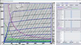
Error in ExtractModel.exe output (V3.0)
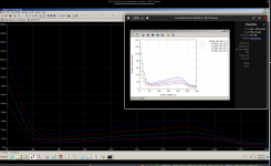
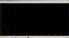
When extracting Spice parameters using the pentode model including secondary emission, there is a term V(9)*KG2 missing in the Spice .cir output file for the screen current G2.
Depending on the model (just check the output file) you need to add V(9)*KG2 as follows:
G2 2 4 VALUE = {0.5*(PWR(V(7),EX)+PWRS(V(7),EX))/KG2 * (1+ als/(1+be*V(1,4)) + V(9)*KG2)}
or
G2 2 4 VALUE = {0.5*(PWR(V(7),EX)+PWRS(V(7),EX))/KG2 *(1+als*Exp(-be*V(1,4) * SQRT(be*V(1,4))) + V(9)*KG2)}
I have discussed this with Derk Reefman, who agrees. It appears as if the gnuplot includes the term but the .cir file does not.
Derk did indicate this would be corrected in the next ExtractModel update.
This only affects the screen current and not the anode current. The images attached show Is with and without the term added.
Attachments
Has someone the model for 2C22 triode? Thanks!
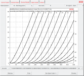
Less precise than Adrian's (kudos), but works well if you just want to use Koren:
Attachments
When extracting Spice parameters using the pentode model including secondary emission, there is a term V(9)*KG2 missing in the Spice .cir output file for the screen current G2.
Depending on the model (just check the output file) you need to add V(9)*KG2 as follows:
Derk did indicate this would be corrected in the next ExtractModel update.
Thanks for this information. Does Derk plan to also update the library file on his website (link below) or do we need to do this on our own?
The uTracer, a miniature Tube Curve Tracer / Tester.
I noticed some other G2 definitions that did not match either of the ones you cited.
Here's my 2C22 model. Works in Micro Cap 11&12 as well as LTspice.
Code:
* ==============================================================
* 2C22 LTSpice model
* Modified Koren model (8 parameters): mean fit error 0.228577mA
* Traced by Wayne Clay on 11/29/2017 using Engauge Digitizer and
* Curve Captor v0.9.1 from RCA data sheet
* ==============================================================
.subckt 2C22  P G K
    Bp  P K  I=
+ (0.04379987792m)*uramp(V(P,K)*ln(1.0+(-0.03130084445)+exp((5.083473539)+
+ (5.083473539)*((19.65907786)+(-146.4566274m)*V(G,K))*V(G,K)/sqrt((37.01007525)**2+
+ (V(P,K)-(14.85637965))**2)))/(5.083473539))**(1.251309236)
    Cgp G P  3.6p
    Cgk G K  2.2p
    Cpk P K  0.7p
    Rpk P K  1.0G ; to avoid floating nodes
    d3  G K  dx1
.model dx1 d(is=1n rs=2k cjo=1pf N=1.5 tt=1n)
.ends 2C22
Attachments
- Home
- Amplifiers
- Tubes / Valves
- Vacuum Tube SPICE Models