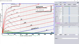
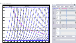
Here is 833 model:
Code:
*** 833A_SOV ** Advanced Grid Current **********************************
* Created on 07/15/2020 19:44 using paint_kit.jar 3.1
* [URL="http://www.dmitrynizh.com/tubeparams_image.htm"]www.dmitrynizh.com/tubeparams_image.htm[/URL]
* Plate Curves image file: 833a-sov.png
* Data source link:
*----------------------------------------------------------------------------------
.SUBCKT 833A_SOV 1 2 3 ; Plate Grid Cathode
+ PARAMS: CCG=3P  CGP=1.4P CCP=1.9P
+ MU=35 KG1=92708.35 KP=757.68 KVB=53609.84 VCT=-23.31 EX=0.914
+ VGOFF=-4.2 IGA=0 IGB=0.089 IGC=876.62 IGEX=1.659
* Vp_MAX=4000 Ip_MAX=5 Vg_step=50 Vg_start=350 Vg_count=10
* Rp=4000 Vg_ac=55 P_max=400 Vg_qui=-48 Vp_qui=300
* X_MIN=37 Y_MIN=36 X_SIZE=837 Y_SIZE=489 FSZ_X=1296 FSZ_Y=736 XYGrid=false
* showLoadLine=n showIp=y isDHT=n isPP=n isAsymPP=n showDissipLimit=y
* showIg1=y gridLevel2=y isInputSnapped=n
* XYProjections=n harmonicPlot=n dissipPlot=n
*----------------------------------------------------------------------------------
E1 7 0 VALUE={V(1,3)/KP*LOG(1+EXP(KP*(1/MU+(VCT+V(2,3))/SQRT(KVB+V(1,3)*V(1,3)))))}
RE1 7 0 1G  ; TO AVOID FLOATING NODES
G1 1 3 VALUE={(PWR(V(7),EX)+PWRS(V(7),EX))/KG1}
RCP 1 3 1G   ; TO AVOID FLOATING NODES
C1 2 3 {CCG} ; CATHODE-GRID
C2 2 1 {CGP} ; GRID=PLATE
C3 1 3 {CCP} ; CATHODE-PLATE
RE2 2 0 1G
EGC 8 0 VALUE={V(2,3)-VGOFF} ; POSITIVE GRID THRESHOLD
GG 2 3 VALUE={(IGA+IGB/(IGC+V(1,3)))*(MU/KG1)*(PWR(V(8),IGEX)+PWRS(V(8),IGEX))}
.ENDS
*$
Attachments
Last edited:
Does anybody have modern (advanced) tube model for 6N1P-EV?
The model I have is some old by Koren.
The model I have is some old by Koren.
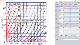
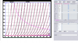
6n1p-ev model:
Code:
**** 6N1P_EV ** Advanced Grid Current **********************************
* Created on 11/12/2020 20:19 using paint_kit.jar 3.1
* [url=http://www.dmitrynizh.com/tubeparams_image.htm]Model Paint Tools: Trace Tube Parameters over Plate Curves, Interactively[/url]
* Plate Curves image file: 6n1p_ev.png
* Data source link:
*----------------------------------------------------------------------------------
.SUBCKT 6N1P_EV 1 2 3 ; Plate Grid Cathode
+ PARAMS: CCG=3.2P  CGP=1.5P CCP=1.5P
+ MU=33 KG1=2603.17 KP=305.48 KVB=57.09 VCT=0.3363 EX=1.792
+ VGOFF=-0.6 IGA=0.00107 IGB=1.614 IGC=44.8 IGEX=1.54
* Vp_MAX=700 Ip_MAX=70 Vg_step=2 Vg_start=12 Vg_count=16
* Rp=4000 Vg_ac=55 P_max=2.2 Vg_qui=-48 Vp_qui=300
* X_MIN=98 Y_MIN=15 X_SIZE=639 Y_SIZE=634 FSZ_X=1296 FSZ_Y=736 XYGrid=false
* showLoadLine=n showIp=y isDHT=n isPP=n isAsymPP=n showDissipLimit=y
* showIg1=y gridLevel2=y isInputSnapped=n
* XYProjections=n harmonicPlot=n dissipPlot=n
*----------------------------------------------------------------------------------
E1 7 0 VALUE={V(1,3)/KP*LOG(1+EXP(KP*(1/MU+(VCT+V(2,3))/SQRT(KVB+V(1,3)*V(1,3)))))}
RE1 7 0 1G  ; TO AVOID FLOATING NODES
G1 1 3 VALUE={(PWR(V(7),EX)+PWRS(V(7),EX))/KG1}
RCP 1 3 1G   ; TO AVOID FLOATING NODES
C1 2 3 {CCG} ; CATHODE-GRID
C2 2 1 {CGP} ; GRID=PLATE
C3 1 3 {CCP} ; CATHODE-PLATE
RE2 2 0 1G
EGC 8 0 VALUE={V(2,3)-VGOFF} ; POSITIVE GRID THRESHOLD
GG 2 3 VALUE={(IGA+IGB/(IGC+V(1,3)))*(MU/KG1)*(PWR(V(8),IGEX)+PWRS(V(8),IGEX))}
.ENDS
*$
Attachments
Thank You, again.
Here are my test results with actual tube (from 2011).
One with low Ia, the other with higher. Same tube.
Here are my test results with actual tube (from 2011).
One with low Ia, the other with higher. Same tube.
Attachments
Last edited:
Does anybody have modern (advanced) tube model for 6N1P-EV?
The model I have is some old by Koren.
artosalo,
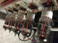
since yesterday I have 5 NOS 6N1P's burning-in, reaching the goal of 100h at the weekend. I will then measure all tubes with my iTracer, select a "golden Sample" out the 5, and generate an i4 model.
This way, I expect to achieve the most accurate 6N1P model this world has ever seen 😀
all the best, Adrian
Attachments
Hi. Are those 6N1P or 6N1P-EV?
I am not sure, but I have understood that - EV types have tighter tolerances.
I am not sure, but I have understood that - EV types have tighter tolerances.
I have 6N1Ps, not the EVs. I have found that the anode currents are in window of +/-7% for my 5 sample, which is quite close.
Hey artosalo,
I have an Ayumi N. model for 6N1P, if that helps. It's from five years ago.
I have an Ayumi N. model for 6N1P, if that helps. It's from five years ago.
Code:
*
* Generic triode model: 6N1P_AN
* Copyright 2003--2008 by Ayumi Nakabayashi, All rights reserved.
* Version 3.10, Generated on Sun Jan 12 18:59:00 2014
*               Plate
*               | Grid
*               | | Cathode
*               | | |
.SUBCKT 6N1P_AN A G K
BGG   GG   0 V=V(G,K)+-0.42063507
BM1   M1   0 V=(0.007566675*(URAMP(V(A,K))+1e-10))**-0.43818786
BM2   M2   0 V=(0.77391879*(URAMP(V(GG)+URAMP(V(A,K))/29.878541)+1e-10))**1.9381879
BP    P    0 V=0.0022884667*(URAMP(V(GG)+URAMP(V(A,K))/38.606817)+1e-10)**1.5
BIK   IK   0 V=U(V(GG))*V(P)+(1-U(V(GG)))*0.0013346379*V(M1)*V(M2)
BIG   IG   0 V=0.0011442333*URAMP(V(G,K))**1.5*(URAMP(V(G,K))/(URAMP(V(A,K))+URAMP(V(G,K)))*1.2+0.4)
BIAK  A    K I=URAMP(V(IK,IG)-URAMP(V(IK,IG)-(0.001233721*URAMP(V(A,K))**1.5)))+1e-10*V(A,K)
BIGK  G    K I=V(IG)
* CAPS
CGA   G    A 1.6p
CGK   G    K 3.2p
CAK   A    K 1.5p
.ENDSHi everybody,
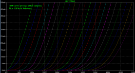
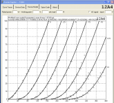
I found a set of curves for 12A4 triode. It looks pretty interesting. (Attached)
I'm wondering if anyone with a curve tracer might be kind enough to whip up an updated model based on these curves. If not, it's OK. Just a request. 🙂
I found a set of curves for 12A4 triode. It looks pretty interesting. (Attached)
I'm wondering if anyone with a curve tracer might be kind enough to whip up an updated model based on these curves. If not, it's OK. Just a request. 🙂
Attachments
Last edited:
Does anyone have E130L tube model ?
We have an interesting discussion going on and I would like to simulate the whole E130L PP-amplifier.
We have an interesting discussion going on and I would like to simulate the whole E130L PP-amplifier.
Hi everybody,
I found a set of curves for 12A4 triode. It looks pretty interesting. (Attached)
I'm wondering if anyone with a curve tracer might be kind enough to whip up an updated model based on these curves. If not, it's OK. Just a request. 🙂
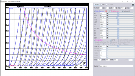
The trace model is up to 400V and missed the other data point in original curve: 500V Vg1=-33 Ig1=0.05mA. I make this appeared in this model:
Code:
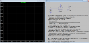
**** 12A4 ** Advanced Grid Current **********************************
* Created on 11/15/2020 11:27 using paint_kit.jar 3.1
* [url=http://www.dmitrynizh.com/tubeparams_image.htm]Model Paint Tools: Trace Tube Parameters over Plate Curves, Interactively[/url]
* Plate Curves image file: 12a4.gif
* Data source link:
*----------------------------------------------------------------------------------
.SUBCKT TRIODE_12A4 1 2 3 ; Plate Grid Cathode
+ PARAMS: CCG=4.9P  CGP=5.6P CCP=0.9P
+ MU=20 KG1=477 KP=168.48 KVB=435 VCT=0.0045 EX=1.484
+ VGOFF=-0.6 IGA=0.001 IGB=0.3 IGC=7.68 IGEX=1.78
* Vp_MAX=700 Ip_MAX=50 Vg_step=2 Vg_start=0 Vg_count=20
* Rp=4000 Vg_ac=55 P_max=6.5 Vg_qui=-48 Vp_qui=300
* X_MIN=87 Y_MIN=49 X_SIZE=734 Y_SIZE=554 FSZ_X=1296 FSZ_Y=736 XYGrid=false
* showLoadLine=n showIp=y isDHT=n isPP=n isAsymPP=n showDissipLimit=y
* showIg1=y gridLevel2=y isInputSnapped=n
* XYProjections=n harmonicPlot=n dissipPlot=n
*----------------------------------------------------------------------------------
E1 7 0 VALUE={V(1,3)/KP*LOG(1+EXP(KP*(1/MU+(VCT+V(2,3))/SQRT(KVB+V(1,3)*V(1,3)))))}
RE1 7 0 1G  ; TO AVOID FLOATING NODES
G1 1 3 VALUE={(PWR(V(7),EX)+PWRS(V(7),EX))/KG1}
RCP 1 3 1G   ; TO AVOID FLOATING NODES
C1 2 3 {CCG} ; CATHODE-GRID
C2 2 1 {CGP} ; GRID=PLATE
C3 1 3 {CCP} ; CATHODE-PLATE
RE2 2 0 1G
EGC 8 0 VALUE={V(2,3)-VGOFF} ; POSITIVE GRID THRESHOLD
GG 2 3 VALUE={(IGA+IGB/(IGC+V(1,3)))*(MU/KG1)*(PWR(V(8),IGEX)+PWRS(V(8),IGEX))}
.ENDS
*$
Attachments
Here is trial model, will update if any issue:Does anyone have E130L tube model ?
We have an interesting discussion going on and I would like to simulate the whole E130L PP-amplifier.
Code:
* [URL="http://www.dmitrynizh.com/tubeparams_image.htm"]www.dmitrynizh.com/tubeparams_image.htm[/URL]
 * Plate Curves image file: E130L.png
* Data source link: <plate curves URL>
*----------------------------------------------------------------------------------
.SUBCKT E130L P G2 G K ; LTSpice tetrode.asy pinout
* .SUBCKT E130L P G K G2 ; Koren Pentode Pspice pinout
+ PARAMS: MU=8.385 KG1=297113.95 KP=53.7 KVB=427.08 VCT=14.24 EX=3.231 KG2=564711.87 KNEE=865.42 KVC=1.948
+ KLAM=3.281E-10 KLAMG=7.089E-4  KD=2136.62 KC=1.346E30 KR1=3.254E-5 KR2=7.823 KVBG=0.000983 KB1=8 KB2=7.04 KB3=2.02 KB4=0.195 KVBGI=0.05472 KNK=-0.03236 KNG=0.006438 KNPL=0.02578 KNSL=0.07314 KNPR=106 KNSR=44.14
+ CCG=35P CGP=2P CCP=17P VGOFF=-0.6 IGA=0.001 IGB=0.3 IGC=8 IGEX=2
* Vp_MAX=300 Ip_MAX=1000 Vg_step=2 Vg_start=0 Vg_count=16
* X_MIN=81 Y_MIN=37 X_SIZE=674 Y_SIZE=560 FSZ_X=1296 FSZ_Y=736 XYGrid=false
* Rp=1400 Vg_ac=20 P_max=27.5 Vg_qui=-15 Vp_qui=300
* showLoadLine=n showIp=y isDHP=n isPP=n isAsymPP=n isUL=n showDissipLimit=y
* showIg1=y isInputSnapped=y addLocalNFB=n
* XYProjections=n harmonicPlot=y dissipPlot=n
* UL=0.43 EG2=150 gridLevel2=y addKink=y isTanhKnee=n advSigmoid=y
*----------------------------------------------------------------------------------
RE1  7 0  1G    ; DUMMY SO NODE 7 HAS 2 CONNECTIONS
E1   7 0  VALUE=  ; E1 BREAKS UP LONG EQUATION FOR G1.
+{V(G2,K)/KP*LOG(1+EXP((1/MU+(VCT+V(G,K))/SQRT(KVB+V(G2,K)*V(G2,K)))*KP))}
RE2  6 0  1G    ; DUMMY SO NODE 6 HAS 2 CONNECTIONS
E2  6 0  VALUE={(PWR(V(7),EX)+PWRS(V(7),EX))} ; Kg1 times KIT current
E4   8 0  VALUE={V(P,K)/KNEE/(KVBGI+V(6)*KVBG)}
E5  81 0  VALUE={PWR(V(8),KB1)}
E6  82 0  VALUE={PWR(V(8),KB2)}
E7  83 0  VALUE={PWR(V(8),KB3)}
E8   9 0  VALUE={PWR(1-EXP(-V(81)*(KC+KR1*V(82))/(KD+KR2*V(83))),KB4)*1.5708}
RE4  8 0  1
RE5 81 0  1
RE6 82 0  1
RE7 83 0  1
RE8  9 0  1
RE21 21 0 1
E21  21 0 VALUE={V(6)/KG1*V(9)} ; Ip with knee but no slope and no kink
RE22 22 0 1 ; E22: kink curr deviation for plate
E22  22 0 VALUE={V(21)*LIMIT(KNK-V(G,K)*KNG,0,0.3)*(-ATAN((V(P,K)-KNPL)/KNSL)+ATAN((V(P,K)-KNPR)/KNSR))}
G1   P K  VALUE={V(21)*(1+KLAMG*V(P,K))+KLAM*V(P,K) + V(22)}
G2   G2 K  VALUE={V(6)/KG2*(KVC-V(9))/(1+KLAMG*V(P,K)) - V(22)}
RCP  P K  1G     ; FOR CONVERGENCE
C1   K G  {CCG}  ; CATHODE-GRID 1
C2   G P  {CGP}  ; GRID 1-PLATE
C3   K P  {CCP}  ; CATHODE-PLATE
RE23 G 0 1G
GG G K VALUE={(IGA+IGB/(IGC+V(P,K)))*(MU/KG1)*
+(PWR(V(G,K)-VGOFF,IGEX)+PWRS(V(G,K)-VGOFF,IGEX))}
.ENDS
*$
Attachments

Thanks for the 12A4 model!
How accurate do you think it is? I couldn't tell from what you wrote about it (my apologies if I misunderstood).
--
How accurate do you think it is? I couldn't tell from what you wrote about it (my apologies if I misunderstood).
--
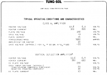
I have made a minor adjustment for 12A4 model so that @500V Vg-33v, Ig is 50uA(0.05mA) as specified in datasheet.
Code:
**** 12A4 ** Advanced Grid Current **********************************
* Created on 11/15/2020 17:25 using paint_kit.jar 3.1
* [URL="http://www.dmitrynizh.com/tubeparams_image.htm"]www.dmitrynizh.com/tubeparams_image.htm[/URL]
* Plate Curves image file: 12a4.gif
* Data source link:
*----------------------------------------------------------------------------------
.SUBCKT 12A4 1 2 3 ; Plate Grid Cathode
+ PARAMS: CCG=4.9P  CGP=5.6P CCP=0.9P
+ MU=20 KG1=477 KP=234.5 KVB=435 VCT=0.0045 EX=1.484
+ VGOFF=-0.6 IGA=0.001 IGB=0.3 IGC=7.68 IGEX=1.78
* Vp_MAX=700 Ip_MAX=50 Vg_step=2 Vg_start=0 Vg_count=20
* Rp=4000 Vg_ac=55 P_max=6.5 Vg_qui=-48 Vp_qui=300
* X_MIN=85 Y_MIN=62 X_SIZE=734 Y_SIZE=554 FSZ_X=1296 FSZ_Y=736 XYGrid=false
* showLoadLine=n showIp=y isDHT=n isPP=n isAsymPP=n showDissipLimit=y
* showIg1=y gridLevel2=y isInputSnapped=n
* XYProjections=n harmonicPlot=n dissipPlot=n
*----------------------------------------------------------------------------------
E1 7 0 VALUE={V(1,3)/KP*LOG(1+EXP(KP*(1/MU+(VCT+V(2,3))/SQRT(KVB+V(1,3)*V(1,3)))))}
RE1 7 0 1G  ; TO AVOID FLOATING NODES
G1 1 3 VALUE={(PWR(V(7),EX)+PWRS(V(7),EX))/KG1}
RCP 1 3 1G   ; TO AVOID FLOATING NODES
C1 2 3 {CCG} ; CATHODE-GRID
C2 2 1 {CGP} ; GRID=PLATE
C3 1 3 {CCP} ; CATHODE-PLATE
RE2 2 0 1G
EGC 8 0 VALUE={V(2,3)-VGOFF} ; POSITIVE GRID THRESHOLD
GG 2 3 VALUE={(IGA+IGB/(IGC+V(1,3)))*(MU/KG1)*(PWR(V(8),IGEX)+PWRS(V(8),IGEX))}
.ENDS
*$
Attachments
This model fit closely 2 operating points specified:
Code:
* [url=http://www.dmitrynizh.com/tubeparams_image.htm]Model Paint Tools: Trace Tube Parameters over Plate Curves, Interactively[/url]
* Plate Curves image file: 12a4.gif
* Data source link:
*----------------------------------------------------------------------------------
.SUBCKT 12A4 1 2 3 ; Plate Grid Cathode
+ PARAMS: CCG=4.9P  CGP=5.6P CCP=0.9P
+ MU=21.56 KG1=372.06 KP=203.5 KVB=690.74 VCT=-0.255 EX=1.469
+ VGOFF=-0.6 IGA=0.001 IGB=0.3 IGC=7.68 IGEX=1.78
* Vp_MAX=700 Ip_MAX=50 Vg_step=4.5 Vg_start=0 Vg_count=39
* Rp=4000 Vg_ac=55 P_max=6.5 Vg_qui=-48 Vp_qui=300
* X_MIN=85 Y_MIN=62 X_SIZE=734 Y_SIZE=554 FSZ_X=1296 FSZ_Y=736 XYGrid=false
* showLoadLine=n showIp=y isDHT=n isPP=n isAsymPP=n showDissipLimit=y
* showIg1=y gridLevel2=y isInputSnapped=n
* XYProjections=n harmonicPlot=n dissipPlot=n
*----------------------------------------------------------------------------------
E1 7 0 VALUE={V(1,3)/KP*LOG(1+EXP(KP*(1/MU+(VCT+V(2,3))/SQRT(KVB+V(1,3)*V(1,3)))))}
RE1 7 0 1G  ; TO AVOID FLOATING NODES
G1 1 3 VALUE={(PWR(V(7),EX)+PWRS(V(7),EX))/KG1}
RCP 1 3 1G   ; TO AVOID FLOATING NODES
C1 2 3 {CCG} ; CATHODE-GRID
C2 2 1 {CGP} ; GRID=PLATE
C3 1 3 {CCP} ; CATHODE-PLATE
RE2 2 0 1G
EGC 8 0 VALUE={V(2,3)-VGOFF} ; POSITIVE GRID THRESHOLD
GG 2 3 VALUE={(IGA+IGB/(IGC+V(1,3)))*(MU/KG1)*(PWR(V(8),IGEX)+PWRS(V(8),IGEX))}
.ENDS
*$
Attachments
Ah, I see that the two curves I found are too different to make one set of curves that adequately represents both. Since there are no published curves in the data sheets, there's some guesswork involved. We have no idea which of the two sets of found curves represents a 'bogey' 12A4, so there's no way to make a single truly representative model. So... Thank you Koonw for your efforts. What you've given us is certain to be useful.
- Home
- Amplifiers
- Tubes / Valves
- Vacuum Tube SPICE Models