Hi jackinnj
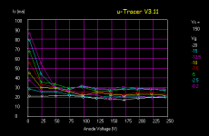
Hmm... may it be that something is wrong with your uTracer ig2 chanel?
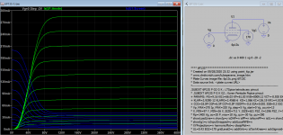
The ig2 graph looks a bit disturbed...
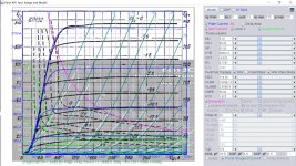
Perhaps it is better to create a model based on the Telefunken datasheet. It even contains ig1 current curves!
What do you think?
Hmm... may it be that something is wrong with your uTracer ig2 chanel?
The ig2 graph looks a bit disturbed...
Perhaps it is better to create a model based on the Telefunken datasheet. It even contains ig1 current curves!
What do you think?
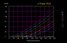
The IG2 curves on both datasheets are very compressed in the region of negative VG1 values. I've checked the current amplifers and voltage amplifers of both Va and Vg2 and they seem to be in close compliance.
The 6360 can be purchased very inexpensively.
Remember that G2 of both sections of the valve are interconnected. The tube, in my practice (in my youth) was used as an output tube @144MHz
The 6360 can be purchased very inexpensively.
Remember that G2 of both sections of the valve are interconnected. The tube, in my practice (in my youth) was used as an output tube @144MHz
Hi Jackinnj
Wow, you worked on HighFrequency tube stuff in your youth? I'm impressed !!
Wow, you worked on HighFrequency tube stuff in your youth? I'm impressed !!
That is a problem for my generic tetrode model, which assumes independent sections. What I can offer is a model valid for both system driven in parallel (both plates connected, both g1 connected)G2 of both sections of the valve are interconnected
Is there a LTSpice tetrode model of the 6P13S tube? ThanksIt works partly. The anode current varies according to the grid voltage at .op-mode, but not at .tran-mode.
Wow, you worked on HighFrequency tube stuff in your youth? I'm impressed !!
So did I, but not intentionally😀
Actually I did build some HF radio stuff with tubes including a big amp with a 4-250, but from age 20 to 62 I worked for Motorola where silicon was free by filling out a sample request form. It also helped that the in house semiconductor sales rep was a ham. My HF, VHF and UHF ham stuff was powered by silicon...or GaAs or GaN.
Hi zintoloThank you Adrian, I was searching tetrode mode model.
I had a short look into the datasheet. As supposed, there are no Ig1 traces (needed to generate a COMPLETE model). So some questions:
1) do you have a sample of this tube available
2) would it be possible to let you measure 7-8 working points of this tube?
Needed stuff:
1 labority supply up to 12V
1 labority supply up to 120V
4 Multimeters
all the best, Adrian
I just googled...cool tube, the 4-125A!So did I, but not intentionally😀
Actually I did build some HF radio stuff with tubes including a big amp with a 4-250 [...]
For me, coping the X00 MHz range with tubes has something magic. The higher the frequency, the stronger the influence of unwanted parasitics, and the harder to understand what's going on...
So did I, but not intentionally😀
Actually I did build some HF radio stuff with tubes including a big amp with a 4-250,
I used the 2E26 quite a bit as they were a fraction of the price of a 6146.
The VHF 6m and 2m converters were those Ameco jobs with the 6CW4's.
The head of the Physics Dept in high school was a ham guy and knew how to get government surplus. We had a drawerful of acorn tubes but no sockets.
I will receive a pair, as I've bought one of those cheap kits with OPTs on pcb to perform some tests.1) do you have a sample of this tube available
Yes, not in a short time unfortunately, but yes.2) would it be possible to let you measure 7-8 working points of this tube?
Needed stuff:
1 labority supply up to 12V
1 labority supply up to 120V
4 Multimeters
I don't have the variable 120V PS. If needed I could arrange something and ask to some friends three multimeters.
Do you think it could be better to have like a signal generator to feed a SE amplifier, a pair of power resistors (to plot points on two different loadlines), an arduino and some voltage dividers to drop all voltages down to 0-5V in order to be read by analog inputs of Arduino and transfer to a laptop?
Like:
- B+ is 400V, voltage divider is 82k 1k (Arduino sees 0-4.8V)
- Plate can swing to 800V, voltage divider is 180k 1k (Arduino sees 0-4.4V)
- Screens will probably be around 150V, let's see 180V max, voltage divider is 39k 1k (Arduino sees 0-4.5V)
- Same voltage divider after the screen stopper to see the drop (so the current)
- one before the grid stopper
- one after the grid stopper for Ig1.
It's six analog inputs of the Arduino to be transferred through USB to a laptop and then exported to Excel.
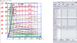
Here is the Paint tool model for 6П13С (6P3S) for sharing:
Code:
**** 6P13S******************************************
* Created on 09/28/2020 23:32 using paint_kip.jar
* [url=http://www.dmitrynizh.com/tubeparams_image.htm]Model Paint Tools: Trace Tube Parameters over Plate Curves, Interactively[/url]
* Plate Curves image file: 6p13c.png 6П13С
* Data source link: <plate curves URL>
*----------------------------------------------------------------------------------
.SUBCKT 6P13S P G2 G K ; LTSpice tetrode.asy pinout
* .SUBCKT 6P13S P G K G2 ; Koren Pentode Pspice pinout
+ PARAMS: MU=9.16 KG1=66.03 KP=61.83 KVB=8009.12 VCT=-8.928 EX=0.7541 KG2=118.39 KNEE=56.04 KVC=1.975
+ KLAM=2.929E-12 KLAMG=2.456E-6  KD=1.066 KC=136.19 KR1=4.103E-5 KR2=0.00278 KVBG=0.408 KB1=2.18 KB2=8028.16 KB3=0.2875 KB4=1.43 KVBGI=2.867 KNK=-0.003195 KNG=0.01106 KNPL=0.5676 KNSL=4.873 KNPR=0.5676 KNSR=49.57
+ CCG=18.8P CGP=6.5P CCP=0.5P VGOFF=-0.6 IGA=0.001 IGB=0.3 IGC=8 IGEX=2
* Vp_MAX=370 Ip_MAX=320 Vg_step=5 Vg_start=0 Vg_count=13
* X_MIN=97 Y_MIN=26 X_SIZE=711 Y_SIZE=621 FSZ_X=1296 FSZ_Y=736 XYGrid=true
* Rp=1400 Vg_ac=20 P_max=18 Vg_qui=-30 Vp_qui=300
* showLoadLine=n showIp=y isDHP=n isPP=n isAsymPP=n isUL=n showDissipLimit=y
* showIg1=y isInputSnapped=y addLocalNFB=n
* XYProjections=n harmonicPlot=y dissipPlot=n
* UL=0.43 EG2=170 gridLevel2=y addKink=y isTanhKnee=n advSigmoid=y
*----------------------------------------------------------------------------------
RE1  7 0  1G    ; DUMMY SO NODE 7 HAS 2 CONNECTIONS
E1   7 0  VALUE=  ; E1 BREAKS UP LONG EQUATION FOR G1.
+{V(G2,K)/KP*LOG(1+EXP((1/MU+(VCT+V(G,K))/SQRT(KVB+V(G2,K)*V(G2,K)))*KP))}
RE2  6 0  1G    ; DUMMY SO NODE 6 HAS 2 CONNECTIONS
E2  6 0  VALUE={(PWR(V(7),EX)+PWRS(V(7),EX))} ; Kg1 times KIT current
E4   8 0  VALUE={V(P,K)/KNEE/(KVBGI+V(6)*KVBG)}
E5  81 0  VALUE={PWR(V(8),KB1)}
E6  82 0  VALUE={PWR(V(8),KB2)}
E7  83 0  VALUE={PWR(V(8),KB3)}
E8   9 0  VALUE={PWR(1-EXP(-V(81)*(KC+KR1*V(82))/(KD+KR2*V(83))),KB4)*1.5708}
RE4  8 0  1
RE5 81 0  1
RE6 82 0  1
RE7 83 0  1
RE8  9 0  1
RE21 21 0 1
E21  21 0 VALUE={V(6)/KG1*V(9)} ; Ip with knee but no slope and no kink
RE22 22 0 1 ; E22: kink curr deviation for plate
E22  22 0 VALUE={V(21)*LIMIT(KNK-V(G,K)*KNG,0,0.3)*(-ATAN((V(P,K)-KNPL)/KNSL)+ATAN((V(P,K)-KNPR)/KNSR))}
G1   P K  VALUE={V(21)*(1+KLAMG*V(P,K))+KLAM*V(P,K) + V(22)}
G2   G2 K  VALUE={V(6)/KG2*(KVC-V(9))/(1+KLAMG*V(P,K)) - V(22)}
RCP  P K  1G     ; FOR CONVERGENCE
C1   K G  {CCG}  ; CATHODE-GRID 1
C2   G P  {CGP}  ; GRID 1-PLATE
C3   K P  {CCP}  ; CATHODE-PLATE
RE23 G 0 1G
GG G K VALUE={(IGA+IGB/(IGC+V(P,K)))*(MU/KG1)*
+(PWR(V(G,K)-VGOFF,IGEX)+PWRS(V(G,K)-VGOFF,IGEX))}
.ENDS
*$
Attachments
Hi zintolo,[...]
Do you think it could be better to have like a signal generator to feed a SE amplifier, a pair of power resistors (to plot points on two different loadlines), an arduino and some voltage dividers to drop all voltages down to 0-5V in order to be read by analog inputs of Arduino and transfer to a laptop?
[...]
why not? Feel free, whatever is faster for you.
(Fastest way: run your sim with Koonw's incomplete model 😀)
all the best, Adrian
Thank you very much! I will use this model by now!Here is the Paint tool model for 6П13С (6P3S) for sharing:
Thank you Adrian, I will do like you suggest, indeed: simulate with the model proposed by Koonw and then arrange that Arduino system to get full data.Hi zintolo,
why not? Feel free, whatever is faster for you.
Here is the Paint tool model for 6П13С (6P3S) for sharing:
Code:**** 6P13S****************************************** * Created on 09/28/2020 23:32 using paint_kip.jar * [URL="http://www.dmitrynizh.com/tubeparams_image.htm"]Model Paint Tools: Trace Tube Parameters over Plate Curves, Interactively[/URL] * Plate Curves image file: 6p13c.png 6П13С * Data source link: <plate curves URL> *---------------------------------------------------------------------------------- .SUBCKT 6P13S P G2 G K ; LTSpice tetrode.asy pinout * .SUBCKT 6P13S P G K G2 ; Koren Pentode Pspice pinout + PARAMS: MU=9.16 KG1=66.03 KP=61.83 KVB=8009.12 VCT=-8.928 EX=0.7541 KG2=118.39 KNEE=56.04 KVC=1.975 + KLAM=2.929E-12 KLAMG=2.456E-6 KD=1.066 KC=136.19 KR1=4.103E-5 KR2=0.00278 KVBG=0.408 KB1=2.18 KB2=8028.16 KB3=0.2875 KB4=1.43 KVBGI=2.867 KNK=-0.003195 KNG=0.01106 KNPL=0.5676 KNSL=4.873 KNPR=0.5676 KNSR=49.57 + CCG=18.8P CGP=6.5P CCP=0.5P VGOFF=-0.6 IGA=0.001 IGB=0.3 IGC=8 IGEX=2 * Vp_MAX=370 Ip_MAX=320 Vg_step=5 Vg_start=0 Vg_count=13 * X_MIN=97 Y_MIN=26 X_SIZE=711 Y_SIZE=621 FSZ_X=1296 FSZ_Y=736 XYGrid=true * Rp=1400 Vg_ac=20 P_max=18 Vg_qui=-30 Vp_qui=300 * showLoadLine=n showIp=y isDHP=n isPP=n isAsymPP=n isUL=n showDissipLimit=y * showIg1=y isInputSnapped=y addLocalNFB=n * XYProjections=n harmonicPlot=y dissipPlot=n * UL=0.43 EG2=170 gridLevel2=y addKink=y isTanhKnee=n advSigmoid=y *---------------------------------------------------------------------------------- RE1 7 0 1G ; DUMMY SO NODE 7 HAS 2 CONNECTIONS E1 7 0 VALUE= ; E1 BREAKS UP LONG EQUATION FOR G1. +{V(G2,K)/KP*LOG(1+EXP((1/MU+(VCT+V(G,K))/SQRT(KVB+V(G2,K)*V(G2,K)))*KP))} RE2 6 0 1G ; DUMMY SO NODE 6 HAS 2 CONNECTIONS E2 6 0 VALUE={(PWR(V(7),EX)+PWRS(V(7),EX))} ; Kg1 times KIT current E4 8 0 VALUE={V(P,K)/KNEE/(KVBGI+V(6)*KVBG)} E5 81 0 VALUE={PWR(V(8),KB1)} E6 82 0 VALUE={PWR(V(8),KB2)} E7 83 0 VALUE={PWR(V(8),KB3)} E8 9 0 VALUE={PWR(1-EXP(-V(81)*(KC+KR1*V(82))/(KD+KR2*V(83))),KB4)*1.5708} RE4 8 0 1 RE5 81 0 1 RE6 82 0 1 RE7 83 0 1 RE8 9 0 1 RE21 21 0 1 E21 21 0 VALUE={V(6)/KG1*V(9)} ; Ip with knee but no slope and no kink RE22 22 0 1 ; E22: kink curr deviation for plate E22 22 0 VALUE={V(21)*LIMIT(KNK-V(G,K)*KNG,0,0.3)*(-ATAN((V(P,K)-KNPL)/KNSL)+ATAN((V(P,K)-KNPR)/KNSR))} G1 P K VALUE={V(21)*(1+KLAMG*V(P,K))+KLAM*V(P,K) + V(22)} G2 G2 K VALUE={V(6)/KG2*(KVC-V(9))/(1+KLAMG*V(P,K)) - V(22)} RCP P K 1G ; FOR CONVERGENCE C1 K G {CCG} ; CATHODE-GRID 1 C2 G P {CGP} ; GRID 1-PLATE C3 K P {CCP} ; CATHODE-PLATE RE23 G 0 1G GG G K VALUE={(IGA+IGB/(IGC+V(P,K)))*(MU/KG1)* +(PWR(V(G,K)-VGOFF,IGEX)+PWRS(V(G,K)-VGOFF,IGEX))} .ENDS *$
The above model lacks of convergence and terminate prematurely, here is the update model:
Code:
**** 6P13S ******************************************
* Created on 09/29/2020 19:34 using paint_kip.jar
* [URL="http://www.dmitrynizh.com/tubeparams_image.htm"]www.dmitrynizh.com/tubeparams_image.htm[/URL]
* Plate Curves image file: 6p13s-2.png
* Data source link: <plate curves URL>
*----------------------------------------------------------------------------------
.SUBCKT 6P13S P G2 G K ; LTSpice tetrode.asy pinout
* .SUBCKT 6P13S_2 P G K G2 ; Koren Pentode Pspice pinout
+ PARAMS: MU=7.837 KG1=356.77 KP=83.92 KVB=3.052 VCT=-0.7963 EX=1.198 KG2=212.62 KNEE=6.534 KVC=1.67
+ KLAM=5.312E-10 KLAMG=1.479E-6  KD=3.076E-6 KC=6.275E-6 KR1=2.839E-4 KR2=0.00905 KVBG=0.08562 KB1=2.989 KB2=2.22 KB3=0.085 KB4=0.3529 KVBGI=0.03757 KNK=-0.03725 KNG=0.01812 KNPL=6.348E-4 KNSL=0.605 KNPR=50.27 KNSR=73.08
+ CCG=17.5P CGP=0.9P CCP=6P VGOFF=-0.6 IGA=0.001 IGB=0.3 IGC=8 IGEX=2
* Vp_MAX=450 Ip_MAX=320 Vg_step=4 Vg_start=0 Vg_count=13
* X_MIN=125 Y_MIN=30 X_SIZE=559 Y_SIZE=568 FSZ_X=1296 FSZ_Y=736 XYGrid=false
* Rp=1400 Vg_ac=20 P_max=18 Vg_qui=-24 Vp_qui=300
* showLoadLine=n showIp=y isDHP=n isPP=n isAsymPP=n isUL=n showDissipLimit=y
* showIg1=y isInputSnapped=y addLocalNFB=n
* XYProjections=n harmonicPlot=y dissipPlot=n
* UL=0.43 EG2=150 gridLevel2=y addKink=y isTanhKnee=n advSigmoid=y
*----------------------------------------------------------------------------------
RE1  7 0  1G    ; DUMMY SO NODE 7 HAS 2 CONNECTIONS
E1   7 0  VALUE=  ; E1 BREAKS UP LONG EQUATION FOR G1.
+{V(G2,K)/KP*LOG(1+EXP((1/MU+(VCT+V(G,K))/SQRT(KVB+V(G2,K)*V(G2,K)))*KP))}
RE2  6 0  1G    ; DUMMY SO NODE 6 HAS 2 CONNECTIONS
E2  6 0  VALUE={(PWR(V(7),EX)+PWRS(V(7),EX))} ; Kg1 times KIT current
E4   8 0  VALUE={V(P,K)/KNEE/(KVBGI+V(6)*KVBG)}
E5  81 0  VALUE={PWR(V(8),KB1)}
E6  82 0  VALUE={PWR(V(8),KB2)}
E7  83 0  VALUE={PWR(V(8),KB3)}
E8   9 0  VALUE={PWR(1-EXP(-V(81)*(KC+KR1*V(82))/(KD+KR2*V(83))),KB4)*1.5708}
RE4  8 0  1
RE5 81 0  1
RE6 82 0  1
RE7 83 0  1
RE8  9 0  1
RE21 21 0 1
E21  21 0 VALUE={V(6)/KG1*V(9)} ; Ip with knee but no slope and no kink
RE22 22 0 1 ; E22: kink curr deviation for plate
E22  22 0 VALUE={V(21)*LIMIT(KNK-V(G,K)*KNG,0,0.3)*(-ATAN((V(P,K)-KNPL)/KNSL)+ATAN((V(P,K)-KNPR)/KNSR))}
G1   P K  VALUE={V(21)*(1+KLAMG*V(P,K))+KLAM*V(P,K) + V(22)}
G2   G2 K  VALUE={V(6)/KG2*(KVC-V(9))/(1+KLAMG*V(P,K)) - V(22)}
RCP  P K  1G     ; FOR CONVERGENCE
C1   K G  {CCG}  ; CATHODE-GRID 1
C2   G P  {CGP}  ; GRID 1-PLATE
C3   K P  {CCP}  ; CATHODE-PLATE
RE23 G 0 1G
GG G K VALUE={(IGA+IGB/(IGC+V(P,K)))*(MU/KG1)*
+(PWR(V(G,K)-VGOFF,IGEX)+PWRS(V(G,K)-VGOFF,IGEX))}
.ENDS
*$
Attachments
Last edited:
- Home
- Amplifiers
- Tubes / Valves
- Vacuum Tube SPICE Models