@richgwilliams Special quality valves such as the Philips E88CC were often specified with the grid biased at a positive voltage with respect to ground and with a cathode resistor that is much larger than the value you would have needed if the grid had been biased at ground.
That's essentially the same as biasing the grid at ground level and connecting the cathode resistor to a negative supply, the only difference being what node you decide to use as a ground reference.
When you let the negative supply approach infinity while also letting the cathode resistor approach infinity to keep the cathode current equal, this circuit approaches current source biasing. Just take the Norton equivalent of the cathode resistor and negative supply to see why.
So despite all the complaints from everyone on this thread, a very rough approximation of current source biasing was actually implicitly recommended for some special quality valves that were used in high reliability equipment.
The Philips E88CC datasheet is remarkably good for a valve datasheet, by the way. It includes lots of information that is missing from a run-of-the-mill valve datasheet, like information on the tolerances of parameters and on the tolerance after 10 000 hours of use.
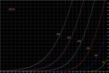
Yes the E88CC that's interesting I will have a good look at its datasheet. It is very similar to the 5670. Here is a characteristic curve for the 5670 showing positive Grid values:
I will say more about current DC bias later on, thanks.
This method of bias was also specified for "wideband" or "baseband" amplifiers, designed to carry the information part of microwave links and other analog era long distance comms. High Gm pentodes were more commonly spec'd, with +9VDC commonly seen for G1, and and appropriately large-ish cathode resistor to give a stable cathode current.
Yes the 5670 was an US manufactured tube specified for military use so I guess they used it for all kinds of jobs including microwaves. I plan to say more about bias later on below, thanks.
Merlin is saying that linearity is highest when you have the flattest loadline, placed as high up and as far towards the left as possible, subject to your not running along the loadline into positive bias territory.
Yes I understand now "lowest distortion therefore occurs with a constant-current load at the highest current and smallest bias" smallest bias meaning low negative Grid values so on the top left of the characteristic curve.
the plate voltage of a triode is constant at idle, when not amplifying...
Yes I was talking about the situation where the Anode to Cathode voltage is forced to a value, lets say 200 Volts all the time with or without signal. Now as signal changes the Grid to Cathode voltage, the only thing that can change is Anode current Ia.
I'm not saying this is useful but its possible, then you get a graph of Anode current versus Grid voltage at constant Anode voltages. Here is the graph of Ia vs Vg at a few values of constant Va 50V 100V 150V 200V 250V 300V for the 5670 Triode:
What it says to me is that the relationship between Grid voltage and Anode current is very non linear at low Anode currents. This graph is the main reason I choose an operating point at 8.192 mA Anode current and 131 Volts Anode voltage. You can see that this point would be as linear as most. You can't go up from here for DC bias because if you choose say 12 mA at 200 Volts yes its linear but it dissipates too much power in the valve/tube. Its 2.4 Watts whereas the Absolute maximum dissipation for each Triode in a 5670 tube is 1.35 Watts.
-
As an example, I've posted an operating point for the 3b7 valve with it biased with a quite high current relative to maximum plate dissipation, towards the left at -1v, as it is only ever going to see +/- 0.5v swing in its input and a relatively flat load line based on the next stage's grid leak.
Yes this is the thinking I have been posting about earlier, have a look at some earlier posts on this thread and the circuit/simulation diagrams. One concern was what would happen if old age pushed the Grid positive of the Cathode. The circuit still works but the Grid starts to draw current. That's not a problem if the input is coming from a modern Opamp that can drive 10mA without blinking.
When you set the average cathode current with your current source, the average anode current will drop when the average grid current increases from practically zero to some nonnegligible value.

But what else can we do? Here are some of my options as far as I see:
- Hold Ip constant - Anode current never changes, Vp the Anode voltage (from Anode to Cathode) at DC bias is fixed but changes as input signal changes.
- Hold Vp constant - Anode voltage (from Anode to Cathode) never changes, Anode current at DC bias is fixed but changes as signal changes.
- Vp and Ip at DC bias cannot change but Vp and Ip can both change as signal changes.
I still have three bias options, Constant current a) Constant voltage b) or Freestyle - best place for linearity c):
Some of you say that constant current is best that's a) above. So I asked, assuming constant current is the relationship between Grid voltage and Anode voltage linear and the answer is - no its non linear. To show this I realised that I needed to plot a third graph for the 5670 tube and the graph is Anode voltage against Grid voltage for lines of constant Anode current for the 5670. So here are the three graphs for the 5670 starting with:
Va vs Vg:
The non linearity is the curvature of the constant current lines, they all curve. Looks like the best places are where Va is between 75 Volts and 200 Volts also where Vg is in the 0 Volts to -3 Volts range. The 12 mA line bends a lot.
Ia vs Vg:
Va vs Ia:
So I still think that this load line is the best place linearity for the 5670 tube:
What you think please?
Attachments
Last edited:
When you set the average cathode current with your current source, the average anode current will drop when the average grid current increases from practically zero to some nonnegligible value.
Yes true. It probably wouldn't be a problem if (because of old age) the Grid went say 0.5 Volts positive of the Cathode the Grid current would still be small.
If you deliberately wanted to use the valve in positive Grid territory a rethink would be needed. Grid current would compete with the constant Anode current that you are trying to achieve.
This method of bias was also specified for "wideband" or "baseband" amplifiers, designed to carry the information part of microwave links and other analog era long distance comms. High Gm pentodes were more commonly spec'd, with +9VDC commonly seen for G1, and and appropriately large-ish cathode resistor to give a stable cathode current. Close enough to a CCS for this demanding gig. For an example, see E180F/6688 or some of the little Russian hot-pants pentodes like 6Zh9Pi or 6Zh11Pi.
The OP should study Merlin's post #51.
All good fortune,
Chris
Yes having had a chance to think about this a lot of tubes were used for telecoms, microwave, line repeaters, telephone switches etc. I don't know about the US but in the UK they used 48 to 52 Volts DC a lot for telecoms so can a tube run at 48 Volts? Looking at the curves again:
Yes 48 VDC is fine and gives good gain at good current if you are happy for the Grid to be in the -1 to +4 Volts range so yes its easy to see why tubes would be run with positive Grids for some applications.
-
Linearity in a single triode stage is quite straightforward. It improves as load impedance increases.....
Linearity may be a consequence of but it is not a direct function of load impedance.
Linearity is a function of positioning on typically the three graphs above Va vs Vg, Ia vs Vg, Va vs Ia
Straightforward maybe but I'm still struggling to see how to find the way to get best linearity.
I've always found these curves more useful.
Yes, more useful than what?
To be honest I don't understand what the gain and transconductance curves are saying about linearity. Other than to say that a fixed value of gain would imply perfect linearity.
The 5670 has modest gain but using local negative feedback to reduce distortion seems like a good idea, even then there is still some THD left over.
As an example for the Transconductance at Va of 100 Volts, Vg of -2 Volts the Transconductance is 2500 microMhos. That's like saying the resistance between Anode and Cathode just there is 400 Ohms.
Last edited:
if you look at the plate curves, they are bent.....To be honest I don't understand what the gain and transconductance curves are saying about linearity. Other than to say that a fixed value of gain would imply perfect linearity.
linearity is reckoned when you get equal spacings of grid voltages from, -1 to -2 to -3 etc...
if you look at the plate curves, they are bent.....
linearity is reckoned when you get equal spacings of grid voltages from, -1 to -2 to -3 etc...
Yes agreed that's why I plotted a graph of Plate voltage against Grid voltage above. The lines of Plate current are curved and that means the equal spaces you mention aren't quite equal.
Your graph appears to be drawn for 150V rather than 48Vcan a tube run at 48 Volts? Looking at the curves again:
Linearity improves as load impedance increases. Whether you call that a cause or an effect is a matter of perspective. Either way, constant-current loading is the irreducible minimum.* Beyond that you enter the upside-down world of distortion cancellation, by using a non-linear load complemetary to the valve curves!Linearity may be a consequence of but it is not a direct function of load impedance.
*There have been attempts to shrink distortion by reducing the heater voltage, to force the curves to 'slump' and produce more equal spacing along a specific load line, but consistency between samples is questionable, and it may adversely affect lifetime.
Not in that form, but you are indirectly potting the constancy of mu. Such graphs were very occasionally published (6SN7):PS I never saw this on any datasheets! Did tube manufacturers ever plot this into datasheets?
Attachments

Last edited:
if you look at the plate curves, they are bent.....
linearity is reckoned when you get equal spacings of grid voltages from, -1 to -2 to -3 etc...
You are right about looking for equal spacings of Grid voltages from -1 to -2 to -3 etc. I plotted this graph to help. On this graph the more equal spacings are the less curved the curves are, and its easier to see curves than equal spaces.
Have a look at this graph:
Not in that form, but you are indirectly potting the constancy of mu. Such graphs were very occasionally published (6SN7):
I agree with you but the graph of Va vs Vg for lines of constant Ia current is more graphic and useful especially if you plan on using constant current.
I don't yet accept that constant current is the most linear.
Your curves appear to be labelled backwards; the 1mA curve should be the 12mA curve. When the labelling is fixed we see the same conclusion: linearity increases at higher constant currents, and smaller bias voltages.
I will check this and replot it. Thanks. I'm just trying to prove or otherwise (maybe to myself) that constant current (constant current at DC bias and when there is input signal) is unconditionally the most linear configuration for a typical Triode. Please bear with me!Your curves appear to be labelled backwards; the 1mA curve should be the 12mA curve. When the labelling is fixed we see the same conclusion: linearity increases at higher constant currents, and smaller bias voltages.
Your curves appear to be labelled backwards; the 1mA curve should be the 12mA curve. When the labelling is fixed we see the same conclusion: linearity increases at higher constant currents, and smaller bias voltages.
Thank you @Merlinb I have corrected the graph of Va vs Vg with lines of constant Anode current Ia. The graph of Anode voltage versus Grid voltage for lines of constant current for the 5670 tube:
And here again the graph of Anode voltage versus Grid voltage for lines of constant current for the 5670 tube showing a typical most linear area:
- Home
- Amplifiers
- Tubes / Valves
- Vacuum Tube bias for designers