the common cathode triode amplifier can be designed for either maximum gain or maximum output swing, this is a basic learning that everyone needs to understand.
so designing triode amps you need to line your ducks in a row, what were you trying to achieve..?
so designing triode amps you need to line your ducks in a row, what were you trying to achieve..?

@TonyTecson
-Minimum noise
-Constant power dissipation due to Anode to Cathode current
-Tight control of DC bias point to avoid poor performance
-Gain with strong local negative feedback to minimise THD
-Recognition that the Grid can be driven from a very high impedance and remain very robust
-A novel new approach to valve circuitry
-Educational material for students on a pro bono basis
-Search for any outstanding valve properties that other devices don't have
-A starting point for others to take further
-An analysis of valve data sheets trying to understand them in modern terms
-Respect for past technology as custodian wishing that the knowledge is not lost
-Assesment of LTspice as a simulator of Thermionic Valves
-Recognition of the 5670 as an excellent military specified valve first manufactured 75 years ago
-A nice sounding audio preamp
I'm happy for anyone to make use of this material. Even to construct equipment around it.
that goes without saying....Minimum noise
there are so many other tubes out there, 5670 is just one of thousands...Recognition of the 5670 as an excellent military specified valve first manufactured 75 years ago
-A nice sounding audio preamp
in the end. it is how you use the tube in the circuit that matter...
it is not the arrows nor the bow, it is up to the Indian making his arrows hit the mark....
@Osvaldo de Banfield
@soulmerchant
@Merlinb
@TonyTecson
I was listening to your comments and I am rethinking my obsession with constant current.
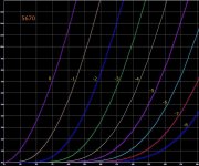
The Triode Ip vs Vp characteristic curves are really difficult to understand (for me) but I got to thinking how to get the best possible linearity?
So here is what my existing circuit does:

But what else can we do? Here are some of my options as far as I see:
So that still lets me choose a "sweet spot" at DC bias and no signal but for those three options I can draw three graphs a) b) and c) as follows:

I'm saying that the circuit will be designed to keep the valve/tube at the same "sweet spot" whether its for a) b) or c). The sweet spot defined as a point where the Cathode current and Anode voltage are both high enough to stay away from non-linearity, keep enough current flowing to stay above noise and keep below the maximum power dissipation. For example if the valve has an absolute maximum Anode to Cathode power dissipation of say 1.35 Watts then I choose a sweet spot at 1 Watt.
Which one of a), b) or c) is best (or going to be most linear)? a), b), c) or something else please?
-
@soulmerchant
@Merlinb
@TonyTecson
I was listening to your comments and I am rethinking my obsession with constant current.
The Triode Ip vs Vp characteristic curves are really difficult to understand (for me) but I got to thinking how to get the best possible linearity?
So here is what my existing circuit does:
But what else can we do? Here are some of my options as far as I see:
- Hold Ip constant - Anode current never changes, Vp the Anode voltage (from Anode to Cathode) at DC bias is fixed but changes as input signal changes.
- Hold Vp constant - Anode voltage (from Anode to Cathode) never changes, Anode current at DC bias is fixed but changes as signal changes.
- Vp and Ip at DC bias cannot change but Vp and Ip can both change as signal changes.
So that still lets me choose a "sweet spot" at DC bias and no signal but for those three options I can draw three graphs a) b) and c) as follows:
I'm saying that the circuit will be designed to keep the valve/tube at the same "sweet spot" whether its for a) b) or c). The sweet spot defined as a point where the Cathode current and Anode voltage are both high enough to stay away from non-linearity, keep enough current flowing to stay above noise and keep below the maximum power dissipation. For example if the valve has an absolute maximum Anode to Cathode power dissipation of say 1.35 Watts then I choose a sweet spot at 1 Watt.
Which one of a), b) or c) is best (or going to be most linear)? a), b), c) or something else please?
-
Attachments
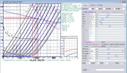
Load up Dmitry Nizhegorodov 's curve painting software and have a play with it.
kind regards
Marek
kind regards
Marek
Load up Dmitry Nizhegorodov 's curve painting software and have a play with it.
kind regards
Marek
Thanks that looks very useful, so it generates spice models from datasheet curves. Will it help me decide?
It not only makes Spice models, but you can also then overlay a plate dissipation curve and put a loadline and operating point onto it. You can then look at H2, H3, H4 curves for that operating point. Although this is just a mathematical analysis based on formulae and the model parameters you enter, it is a good starting point when looking at dynamics of how different non-linearities pan out, depending on where your operating point is and how steep your loadline is.
The real world will of course add its own real world complexity on top of this, so don't hang your hat on any one particular "truth".
kind regards
Marek
The real world will of course add its own real world complexity on top of this, so don't hang your hat on any one particular "truth".
kind regards
Marek
Attachments
I never saw this done before until I designed it.
A negative rail on the cathode is nothing new (and you did not answer my question). Your circuit is incomplete if you are using a constant current sink. If you are using a negative rail, then I see more drawbacks to your schematic.
Merlin touched on them. His advice is spot on. His books are worth reading. Also, TonyTecson really knows his stuff as well.
You found a small window where if you sacrifice a lot of gain, you can get a linear response. I would say if you like it, then keep it that way.
If you want to use a common valve/tube that is very linear, quite common and won't disappoint - I suggested the bog-standard 6SN7 already. If you want, others can also be suggested. ECC88 is a another very good one for a bit more gain.
As Tony noted, there are literally thousands of choices...
Last edited:
That's very useful. In the real world of Triodes the square space of Ip vs Vp will be the same for a given tube type number. What changes is how Grid voltage curves map to that space.
Seems that mathematically it should be possible to calculate the most linear line the curves will allow.
Seems two things, how curved curves are and how uniform is the Grid voltage between curves.
Mathematics beyond me, something like finding the straight line of minimum gradient in two dimensions.
Then there is what happens if we want to go from Grid voltage signal to amount of power out.
Thanks for the advice.
Last edited:
Linearity in a single triode stage is quite straightforward. It improves as load impedance increases, and it improves as the bias is made hotter. The lowest distortion therefore occurs with a constant-current load at the highest current and smallest bias you can safely get away with.
Noise does not follow such simple rules, but that only matters in the input stage.
Noise does not follow such simple rules, but that only matters in the input stage.
Yes it looks the same and same maximum power dissipation per Triodes. Thanks.Looks like the curves of a 6922. Very nice tube
Yes so curve a) in my post #45. But curve c) looks better and it is close to constant current but not exactly. What do you mean by "highest current and smallest bias" ? I understand highest current as away from where the curves really curve but smallest bias?Linearity in a single triode stage is quite straightforward. It improves as load impedance increases, and it improves as the bias is made hotter. The lowest distortion therefore occurs with a constant-current load at the highest current and smallest bias you can safely get away with.
Noise does not follow such simple rules, but that only matters in the input stage.
Triodes are Thevenin circuit type, plate current is controlled by grid voltage....
Tetrodes, pentodes, are Norton types, plate current is controlled by either grid voltage or g2 voltages..
you need a varying plate voltage to make an ac voltage swing...
how much you can swing the plate voltage is your peak to peak ac swing, between cutoff(b+ plate supply voltage) and saturation volts (around 50 volts)
Last edited:
you need a varying plate voltage to make an ac voltage swing...
Not true, input AC swing can cause output AC current swing while the voltage between Anode and Cathode is held fixed at a constant value.
The valve characteristic curves allow that.
@richgwilliams Special quality valves such as the Philips E88CC were often specified with the grid biased at a positive voltage with respect to ground and with a cathode resistor that is much larger than the value you would have needed if the grid had been biased at ground.
That's essentially the same as biasing the grid at ground level and connecting the cathode resistor to a negative supply, the only difference being what node you decide to use as a ground reference.
When you let the negative supply approach infinity while also letting the cathode resistor approach infinity to keep the cathode current equal, this circuit approaches current source biasing. Just take the Norton equivalent of the cathode resistor and negative supply to see why.
So despite all the complaints from everyone on this thread, a very rough approximation of current source biasing was actually implicitly recommended for some special quality valves that were used in high reliability equipment.
The Philips E88CC datasheet is remarkably good for a valve datasheet, by the way. It includes lots of information that is missing from a run-of-the-mill valve datasheet, like information on the tolerances of parameters and on the tolerance after 10 000 hours of use.
Last edited:
This method of bias was also specified for "wideband" or "baseband" amplifiers, designed to carry the information part of microwave links and other analog era long distance comms. High Gm pentodes were more commonly spec'd, with +9VDC commonly seen for G1, and and appropriately large-ish cathode resistor to give a stable cathode current. Close enough to a CCS for this demanding gig. For an example, see E180F/6688 or some of the little Russian hot-pants pentodes like 6Zh9Pi or 6Zh11Pi.
The OP should study Merlin's post #51.
All good fortune,
Chris
The OP should study Merlin's post #51.
All good fortune,
Chris
Merlin is saying that linearity is highest when you have the flattest loadline, placed as high up and as far towards the left as possible, subject to your not running along the loadline into positive bias territory.
As an example, I've posted an operating point for the 3b7 valve with it biased with a quite high current relative to maximum plate dissipation, towards the left at -1v, as it is only ever going to see +/- 0.5v swing in its input and a relatively flat loadline based on the next stage's grid leak.
Note that both what is driving it at the input and what it is driving at its output are both constraints on "design".
It's just an exercise example. In the real world, you'll have to design to give yourself a margin for error and component tolerance, think about layout, power supplies....
kind regards
Marek
Not true, input AC swing can cause output AC current swing while the voltage between Anode and Cathode is held fixed at a constant value.
The valve characteristic curves allow that.
the plate voltage of a triode is constant at idle, when not amplifying...
- Home
- Amplifiers
- Tubes / Valves
- Vacuum Tube bias for designers