You are trying to force the valve/tube to 'stay on' by using a constant current sink. This is not new. There are different ways to force the valve/tube to stay on. You probably have read about them all.
The current from Plate to Cathode (without AC signal) is always accurately 8.192mA the voltage across the 1K5 Cathode resistor is quite large usually maybe as much as 10 Volts, the HT (B+) is hopefully exactly 180 Volts so the Voltage at the Plate (without AC signal) is exactly 180 - (6000 x 8.192 e-3) which is 130.85 Volts exactly.
You can do that even with a non-bypassed cathode resistor referenced to ground if you know what you are doing and understand the electrical characteristics of your triode well. You can also simply bias the grid - which is the standard way which plate curves in datasheets are generated (measured then averaged. This is often done in pro audio.
Are you using a constant current sink to bias the cathode? or just a negative rail? It seriously is not new - pretty much everything has been done before with valves/tubes. But they are still a pleasure to work with 😉
Are you using a constant current sink to bias the cathode? or just a negative rail? It seriously is not new - pretty much everything has been done before with valves/tubes. But they are still a pleasure to work with 😉
Last edited:
As a designer the whole point is not for my design to rely on the characteristic curves to stay constant during the lifetime of the valve, to stay constant between different valves of the same type or to be the same for different valve types.
That's the whole point of this design method, constant current and negative rail to allow the emitter resistor to hold the Cathode slightly positive of the DC Grounded Grid.
I never saw this done before until I designed it. Show me a circuit where it is done? If it had been used in equipment from many years ago it would have solved countless reliability problems and so many posts in diyaudio about the need to adjust Grid bias resistance etc.
If you build valve circuitry try it.
Last edited:
This perhaps tells us something about its utility...I never saw this done before until I designed it.
CCS bias is not unknown, but it is uncommon. The devil is in defining to what problem it is a solution. If the anode was DC coupled to the opamp then there is a good argument for it, because it will hold the DC anode voltage constant forever. It may also be useful in a power output stage to maintain constant dissipation. But for an AC coupled stage as you have shown, why would we want the current to remain constant? With CCS bias, as the valve ages the input headroom will shrink. By contrast, cathode bias will to some extent maintain the same bias point relative to the available swing on the load line, and fixed bias will maintain the same headroom. But why CCS bias?
Last edited:

CCS bias is not unknown, but it is uncommon. The devil is in defining to what problem it is a solution. If the anode was DC coupled to the opamp then there is a good argument for it, because it will hold the DC anode voltage constant forever. It may also be useful in a power output stage to maintain constant dissipation. But for an AC coupled stage as you have shown, why would we want the current to remain constant? With CCS bias, as the valve ages the input headroom will shrink. By contrast, cathode bias will to some extent maintain the same bias point relative to the available swing on the load line, and fixed bias will maintain the same headroom. But why CCS bias?
I will think about what you say, you understand the circuit.
What makes you say that as the valve ages the input headroom will shrink? I have tried large shifts in the Grid bias voltage and no change, the circuit still passes 8.192 mA with the Anode staying at 131 Volts.
All the original specification sheets for the 5670 quote 8mA and 150 Volts as important
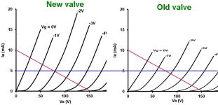
Because as the valve ages its characteristics 'slump', i.e. gm declines. Here's a ghetto sketch to illustrate the point. By keeping the bias current at 5mA for example (blue line), the bias point moves from 2V when new, to about 1.5V when old, so we have lost headroom.What makes you say that as the valve ages the input headroom will shrink?
The datasheet gives some typical operating conditions, but they are not 'important' for any particular reason.All the original specification sheets for the 5670 quote 8mA and 150 Volts as important
Attachments
Last edited:
in the past, source resistances were high so that high value grid leaks are a must...
not anymore, with today's source resistance that are low, no need to use high values of grid leak resistors...
not anymore, with today's source resistance that are low, no need to use high values of grid leak resistors...
Because as the valve ages its characteristics 'slump', i.e. gm declines. Here's a ghetto sketch to illustrate the point. By keeping the bias current at 5mA for example (blue line), the bias point moves from 2V when new, to about 1.5V when old, so we have lost headroom.
The datasheet gives some typical operating conditions, but they are not 'important' for any particular reason.
Thank you that's interesting to know. I design around what the datasheets say rather than allow for old devices but I see what you are saying. There are several datasheets from several manufacturers for the 5670 valve type.
Here is an extract from a 1956 GE datasheet:
The typical operation is telling me that with an Anode voltage of 150 Volts and an Anode to Cathode current of 8.2 mA is OK long term. With 8.2 mA through the 240R Cathode resistor the Cathode is 8.2 e-3 x 240 Volts more positive than the Grid. That's a Grid voltage of -1.968 Volts. Studying the several datasheets I'm confident that at 8.192mA and 130V Anode voltage I have a Grid at about -2 Volts negative. So allowing for the slump you describe and my signal input of 1 Volt peak I have a Grid voltage headroom of 1 Volt before the Grid is starting to reach 0 Volts.
@TonyT1603 has reminded us (thank you) that the source resistance presented to the input by modern equipment is low (and often DC coupled accurately around 0V) so Grid leakage current is not a problem.
The Cathode Resistor Bias method you praise cannot work when the Grid needs to be positive of the Cathode so you have helped to point out one of the great advantages of my design. That is it is quite happy to pull the Cathode below 0V and allow the Grid to go positive relative to the Cathode and still maintain that DC bias point of 8.192mA Anode to Cathode current and 131 Volts Anode voltage.
Also the 5670 valve is quite happy to work with positive Grid voltages, here is the characteristic curves again from the same GE datasheet:
This characteristic curve goes up to +1 Grid voltage but other GE curves go from -10 Volts to +6 Volts Grid voltage. It also shows that linearity is much the same so THD will remain good.
The 5670 was an US manufactured tube/valve specified by the military and manufactured by GE, Raytheon and others.
to those starting out with tube designs, the tube data sheet gives you all you need to go...
but do not bet that in your actual build, when you design for say 5ma plate current, expect to find 3 or 7 ma, this is not surprising....
but do not bet that in your actual build, when you design for say 5ma plate current, expect to find 3 or 7 ma, this is not surprising....
to those starting out with tube designs, the tube data sheet gives you all you need to go...
but do not bet that in your actual build, when you design for say 5ma plate current, expect to find 3 or 7 ma, this is not surprising....
Yes datasheets mostly quote typical values unless they are giving minimum or maximum values.
This is the whole idea of my circuit given in post #3 It does not care about variations you will not need to expect to find 3, 5 or 7 mA - the Anode to Cathode DC bias current will be and will stay at 8.192 mA exactly.
Yes your CCS would be happy, but the signal source may not be! 😳 When would you need to bias the grid positive? Is the end goal a Class A2 power amp?The Cathode Resistor Bias method you praise cannot work when the Grid needs to be positive of the Cathode so you have helped to point out one of the great advantages of my design. That is it is quite happy to pull the Cathode below 0V and allow the Grid to go positive
Yes, provided you have a signal source that is happy driving the highly nonlinear grid current.It also shows that linearity is much the same so THD will remain good.
Last edited:
Yes your CCS would be happy, but the signal source may not be! 😳 When would you need to bias the grid positive?
You don't read posts or understand the circuit that's obvious. If what you described happened as regards ageing the circuit would still maintain the DC bias current of 8.192 mA and the Grid would become positive of the Cathode if necessary. It's in a feedback loop for DC bias. So the valve would be in the part of it's characteristics that show positive Grid curves and it's linear there.
@TonyTecson has already reminded us that modern equipment is mostly happy providing drive to other equipment so it would provide plenty of drive to supply any increased Grid leakage current.
Please go and muddy someone else's thread.
The anode curves are linear, but the grid current is not. There is an invisible diode between grid and cathode; once the bias exceeds 0V and goes positive, the input resistance of the grid rapidly drops to a few hundred ohms, typically. When the grid is 1V positive of the cathode you might have 1mA of DC flowing into the grid. Most signal sources are AC coupled so cannot supply any DC, and many would struggle to drive a signal into such a low impedance load even if positive bias was acheived. There's nothing wrong with CCS bias in principle, it has special applications like anything else, but preamp stages are rarely one of them.So the valve would be in the part of it's characteristics that show positive Grid curves and it's linear there.
Last edited:
What Merlin is saying is that anytime you approach or pass to the right hand side of the 0v bias line, you need to look at a datasheet graph which is augmented with grid current data to understand not just the plate voltage characteristic, but additionally the current needed to be sourced from the previous output stage.
For example, for your valve, the graph needs the extra dashed lines shown below:-

When the bias is 2v positive, the dashed line shows the valve is attempting to sink ~2.5mA into its grid from whatever signal is driving its grid; when biased to +4v, the grid will sink ~6mA from the previous stage; when the bias is 6v positive, the valve is attempting to sink a whopping 10-11mA into the grid from the previous stage.
Whatever drives a 5670 stage has to be capable of supplying that current if you want to go to that part of the plate curve. Note also as plate voltage drops, demand for grid current goes up.
kind regards
Marek
For example, for your valve, the graph needs the extra dashed lines shown below:-
When the bias is 2v positive, the dashed line shows the valve is attempting to sink ~2.5mA into its grid from whatever signal is driving its grid; when biased to +4v, the grid will sink ~6mA from the previous stage; when the bias is 6v positive, the valve is attempting to sink a whopping 10-11mA into the grid from the previous stage.
Whatever drives a 5670 stage has to be capable of supplying that current if you want to go to that part of the plate curve. Note also as plate voltage drops, demand for grid current goes up.
kind regards
Marek
It should be added that almost no one bothers to consider grid current when they submit Spice models. Pretty much all of the models just assume the grid will be of infinite impedance come what may so the grid leak resistor is all that matters. I think Adrian Immler is the only person who submits models based on more than just the most basic datasheet V-I curves. That means most sims using LTSpice don't even attempt to tell the truth when going onto that part of the plate curves.
kind regards
Marek
kind regards
Marek
this is reason i do not put too much faith in simulations.....It should be added that almost no one bothers to consider grid current when they submit Spice models. Pretty much all of the models just assume the grid will be of infinite impedance come what may so the grid leak resistor is all that matters. I think Adrian Immler is the only person who submits models based on more than just the most basic datasheet V-I curves. That means most sims using LTSpice don't even attempt to tell the truth when going onto that part of the plate curves.
kind regards
Marek
to avoid this, do not use input signals that will make the grid go into positive region...What Merlin is saying is that anytime you approach or pass to the right hand side of the 0v bias line, you need to look at a datasheet graph which is augmented with grid current data to understand not just the plate voltage characteristic, but additionally the current needed to be sourced from the previous output stage.
For example, for your valve, the graph needs the extra dashed lines shown below:-
View attachment 1329567
When the bias is 2v positive, the dashed line shows the valve is attempting to sink ~2.5mA into its grid from whatever signal is driving its grid; when biased to +4v, the grid will sink ~6mA from the previous stage; when the bias is 6v positive, the valve is attempting to sink a whopping 10-11mA into the grid from the previous stage.
Whatever drives a 5670 stage has to be capable of supplying that current if you want to go to that part of the plate curve. Note also as plate voltage drops, demand for grid current goes up.
kind regards
Marek
true, the plate resistance at plate voltage, the plate load resistors and the next stage grid leak are all in parallel....DC 'sweet spot' also depends on the load and the valve/tube you are working with.
BTW - Looking at your chosen plate curve, I see you are losing a lot of gain. Clearly with such a low plate load, you don't want to get into the 'knees' which will happen really fast if you bias further negative for your 5670.
Some valves/tubes are really linear across a wider range. Some are just nasty to try and deal with as Triodes. Some pentodes are astonishingly linear, while not linear at all when triode strapped. That's part of the fun in this hobby.
so the combination of these resistors devided by (1/gm + 1.5k) is your voltage gain, which is quite low compared to the tube's mu,
This is reason I do not put too much faith in simulations.....
After many years of using spice simulators you get a good feeling about how well a simulator is working. Currently the Analog Devices LTspice simulator is an excellent product and I recommend it.
Whenever I can I use Analog Devices LTspice models or device manufacturer LTspice models. Third party spice models - use with caution, valve spice models - use with even more caution.
For example to develop Active Triode Bias I have tested many 5670 Triodes on the bench and cross checked with datasheets and spice models. To develop I used three different LTspice models for the 5670 Triode tube. One of the spice models stood out as being a very close fit to datasheet characteristic curves.
This best fit model I rewrote into two versions, the standard version and a simplified version.
Why a simplified version? Well the simulations run faster when there are a lot of tubes to simulate etc.
Here is the standard LTspice model that I use for the GE 5670 Triode tube:
.subckt 5670 1 6 3 params: mu=40.9 ex=1.71 kg1=825 kp=126 kvb=708 rgi=2000 vct=.01 ccg=2.3p cgp=1.3p ccp=1.3p
e1 7 0 value= {v(1,3)/kp*log(1+exp(kp*(1/mu+v(2,3)/sqrt(kvb+v(1,3)*v(1,3)))))}
re1 7 0 1g
g1 1 3 value= {(pwr(v(7),ex)+pwrs(v(7),ex))/kg1}
rcp 1 3 1g
c1 2 3 {ccg}
c2 1 2 {cgp}
c3 1 3 {ccp}
r1 2 5 {rgi}
v1 5 6 {vct}
d3 6 3 dx
.model dx d(is=1n rs=1 cjo=1pf tt=1n)
.ends
Here is the simplified LTspice model that I use:
.subckt 5670 A G K params: mu=40.9 ex=1.71 kg1=825 kp=126 kvb=708
*Quiescent current
e1 7 0 value= {v(A,K)/kp*log(1+exp(kp*(1/mu+v(G,K)/sqrt(kvb+v(A,K)*v(A,K)))))}
*Voltage dependence
g1 A K value= {(pwr(v(7),ex)+pwrs(v(7),ex))/kg1}
.ends
To be certain that Active Triode Bias worked I tried different valve types and different DC bias circuitry and attach some draft circuits as follows:
Have a look at this thread, see what you think:
Active Triode Bias
Last edited:
- Home
- Amplifiers
- Tubes / Valves
- Vacuum Tube bias for designers