Your graph appears to be drawn for 150V rather than 48V
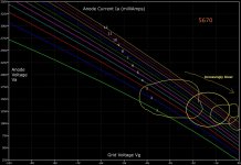
I didn't draw the blue cross at 150 Volt it is just there on my datasheet. I was making the point that a valve like the 5670 could be used on telecoms systems running at 48 Volt provided positive Grid voltages are allowed, the 5670 is certainly well specified at positive Grid voltages.
Linearity improves as load impedance increases. Whether you call that a cause or an effect is a matter of perspective.
Its a kind of cart before the horse situation, I would argue that the the graph of Anode voltage versus Grid voltage for lines of constant current comes first and load impedance must allow its constraints. Another way of looking at it is that I don't understand impedances and transconductances too well lol.
*There have been attempts to shrink distortion by reducing the heater voltage......
I don't want to go there, I'm just trying to understand (and prove if) constant Anode to Cathode current (when with or without signal) is the very most linear option for a Triode such as the 5670.
Not in that form, but you are indirectly potting the constancy of mu.
I take your word for it, being truthful I'm struggling to understand what the mu and transconductance curves are telling me especially since they are drawn for lines of constant Anode voltage.
Thanks for your replies, I can see that you understand a great deal about how tubes/valves work - more than I do that's for sure.
That said I'm already beginning to feel a pain when I see other Triode designs (when the Triode is used as input) biased with a 100K Anode resistor and a 500R Cathode resistor in parallel with a 100uF capacitor!
Best regards.
OK good. The higher the current, the more linear the curve. And the smaller the bias, the more linear is that section of curve. Each circle contains ever more linear operation, with the upper-most single curve (constant current) as the final conclusion.
Yes looks good, I have two boundary conditions as follows, 1) The product of Va Ia must stay within the allowed dissipation. For the 5670 I was working on 1 Watt per Triode in the two Triode valve. 2) Don't want the Grid voltage to be more positive than say -2 Volts, that allows for signal and characteristics spread and drift over time.