a dual 25Vac transformer will generate ~37Vdc on a lower bias ClassAB amplifier.
Expect a couple of volts less into a Full ClassA amplifier.
That gets your caps down to ~+35Vdc.
Then add on 10% for max mains tolerance and your 40Vdc is still not exceeded.
But what if the amplifier is disconnected? How high will your 25Vac transformer take the PSU when loading is open circuit?
Thank you AndrewT
I have the diyAudio Store Soft start and speaker delay boards that will be installed to cover turn on inrush. I will grab 16 of the 33000mf 40volt Mundorfs from Partsconnexion. I will also see what bridge rectifiers they have that may work as well.
Todd
Good Day
The recommended rectifier diodes will not be in stock at Mouser or Digikey until June/July- maybe. Would the following be a suitable replacement? Digi-key Part number
VS-60CPU02-N3GI-ND.
Thank you
The recommended rectifier diodes will not be in stock at Mouser or Digikey until June/July- maybe. Would the following be a suitable replacement? Digi-key Part number
VS-60CPU02-N3GI-ND.
Thank you
I am almost ready to solder up my PS boards for the F5 Turbo. I want to make sure I am doing things correctly. I am building a full dual mono stereo amp in a Deluxe 5U chassis.
I have two 1000VA 24v secondary Plitron transformers. I have two universal PS boards with 16 Mundorf caps along with a set of DIY speaker protect/soft start for each channel. Do I fully populate both PS boards(all resistors) including all of the the rectifier boards? The idea being one Universal PS board per channel.
Any advice would be greatly appreciated as I want to do this correct the first time out.
Thanks
Wire up your transformer first.
Power it up via a Mains Bulb Tester (MBT). Check the voltages are correct.
Then add on the bridge rectifier. Power up via MBT. Check voltages.
Add on the Smoothing Capacitors. Power up via MBT. Check voltages.
Once you have capacitors fitted you must discharge them (every time) using a resistor after testing.
Add on one channel of amplifier. Check that the VR are set to draw minimum output current. Power on via MBT. Check voltages.
Last edited:
Hi AndrewT
At this point, I am more concerned that I am building the correct version of the power supplies for the intended purpose. Do I need all 4 rectifiers per board? Or would it be better to purchase two bridges and not use the rectifiers at all?
Thanks
At this point, I am more concerned that I am building the correct version of the power supplies for the intended purpose. Do I need all 4 rectifiers per board? Or would it be better to purchase two bridges and not use the rectifiers at all?
Thanks
Todd,
as I read it you got yourself some premium caps for the PSU, so I would populate the diodes on the PSU board if I was you.
You can also skip that and use 2 simple diode bridges as in one of the build guides.
Both will work.
Generally speaking I think it might be better to ask amp specific question in the corresponding amp thread, you'll have hundreds of people having build one for the F5T ...
Please confirm you have dual secondaries on your piltorns (2 x 24V) and not 24V as you mentionned....
Cheers,
Max
Thanks for the advice.
I do have dual secondaries. I also want to confirm my selection of rectifier diodes as the 863-MBR20200CTG are 20A 200V where as 6L6 indicates that we should use a 30A 200V minimum. Therefore I have got my sights on the following two alternatives and am wondering which would be the best to use. VS-60CPU02-N3GI-ND or DSSK-02A-ND. Once I get the PS squared away, I will ask questions in the amp forum as I do have a few.
Todd
Todd,
any diode will work, if 6L6 insists on 30A then pls follow his advice. I suppose most of the F5T builders just order more of the MUR3020 (for Turbo V2 /V3) which is a 30A Diode...
The 2 you mentionned will work.
https://www.mouser.com/ds/2/427/vs-mur3020w-87514.pdf
Feel free to pay more for faster/"better" ... but I doubt you will have any benefit.
The diode discussion goes on for years, you should find some info here on the forum using the search function.
Cheers,
Max
Last edited:
Thanks for the advice.
I have purchased 16 of the MUR3020 diodes that you recommend. I don't need to go looking for better/faster. That pretty much takes care of the power supplies.
Todd
I have purchased 16 of the MUR3020 diodes that you recommend. I don't need to go looking for better/faster. That pretty much takes care of the power supplies.
Todd
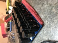
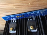
No voltage output forgot the cut Center 3rd leg of diode
18 V in 0 V out also noticed drop resistor for LED runs burning hot was smoking a little.
I think I noticed my mistake my diode package was the T03, I was getting carried away with soldering looking back at the photos illustration guide I noticed on the TO220 package diode’s the center leg was cut off on my board I left the center leg on my diode’s is this my problem ?.
Taking voltage out readings at AC 1A and AC 1B
Attachments
If i need +/-15Vdc, it will be used for a passive crossover and bass EQ circuit with op-amps. Will a 2 x 12 Vac trafo be in the right ballpark with this board?
I'd like to use the PSU board to build the Pearl 2. I can find a few examples of where people have done this, but none where it is explained how to go from Wayne's example PSU to the Universal PSU board. It is very obvious that the Universal PSU board is a real Swiss army knife, but the actual BOM of the board and how to stuff the board isn't obvious to me.This is my first build that involves a PSU and my second build ever. I've spent a fair amount of time reading the different threads and I'm only more confused. Can someone point me in the right direction to get me started? Thanks,
Ask in pass labs forum.
You will get a faster response to your question.
I would help but I need to go back to sleep.
You will get a faster response to your question.
I would help but I need to go back to sleep.
Jim
Is there even the remote possibility of integrating a soft start circuit using a secondary 24V transformer on the PSU PCBs, thus enabling the use of a momentary contact switch rated for 24V, as it would be safer than having mains rated push button switch on the front panel.
Just thinking out loudly, not volunteering for the new design, mind you.
I'm trying to educate myself on linear power supplies as I'll probably need to build one sooner or later.
I just read this article which mentions that usually the smoothing section is followed by a regulator section. Now I can't make out where the regulator sections is on this circuit board. Can someone point me in the right direction?
I just read this article which mentions that usually the smoothing section is followed by a regulator section. Now I can't make out where the regulator sections is on this circuit board. Can someone point me in the right direction?
Henry- there is discussion of a new soft start that might incorporate something like that. Any ideas you have would be welcome in the discussion.
Mixi- there’s no regulator section on this board, instead the smoothie and filtering section is completely enormous. Also power amps Very rarely have regulated supplies because the heat sink requirements is usually close to that of the amplifier…
Mixi- there’s no regulator section on this board, instead the smoothie and filtering section is completely enormous. Also power amps Very rarely have regulated supplies because the heat sink requirements is usually close to that of the amplifier…
Sorta yes. It’s more complicated than that but generally speaking a power amp won’t be regulated.
Henry- there is discussion of a new soft start that might incorporate something like that. Any ideas you have would be welcome in the discussion.
Mixi- there’s no regulator section on this board, instead the smoothie and filtering section is completely enormous. Also power amps Very rarely have regulated supplies because the heat sink requirements is usually close to that of the amplifier…
Thanks Jim. I will have a look at that.
- Home
- The diyAudio Store
- V3 Universal Power Supply Circuit Board