I have ordered two psu boards since i want a dual mono design for my honey badger amplifier. However, I can't figure out the rs1, rs2, cx1, cx2, cs1, cs2 (input snubber capacitors and resistors) values. I tried to read the suggested paper in the bom but I couldn't understand it. I am planning to use two 45-0-45 400VA transformers (one for each channel). Can you help me determine the ideal values for the aforementioned components?
Quasimodo results (ONLY)
Quasimodo is a math based test app to determine the right values for snubbers...the thread above posts those results, you may be lucky enough to find yours. It does seem that Cx 0.01mF. , Cs 0.15mF and R 18 ohms are good enough generic values but I am no expert and you should check this out ( they worked for me and Antek 300 VA transformer )
Quasimodo is a math based test app to determine the right values for snubbers...the thread above posts those results, you may be lucky enough to find yours. It does seem that Cx 0.01mF. , Cs 0.15mF and R 18 ohms are good enough generic values but I am no expert and you should check this out ( they worked for me and Antek 300 VA transformer )
Hi....most power supplies are of the Switched Mode Power Supply (SMPS) type, factors in selecting an SMPS will be the topic here. When selecting an SMPS, you will need to know input voltage, output voltage, maximum current draw, form factor, and purpose (for regulatory reasons) of the power supply.
Universal Power supply board
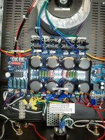
A question or two on what voltages I should be reading mainly at the 24VDC end of the power supply board. Attached is picture and some values. When I read 67VDC from 24+ across to 24- did not think I wanted to hook up the aleph j boards. If I hook up the two aleph j boards will that make the DC voltage correct? As it is with yellow wire -24VDC to red wire +24VDC I would have the measured 67~VDC to the boards and would be fried.Yes don't look at the soft start resistors as they came that way. (cough cough) Thanks for any input.
A question or two on what voltages I should be reading mainly at the 24VDC end of the power supply board. Attached is picture and some values. When I read 67VDC from 24+ across to 24- did not think I wanted to hook up the aleph j boards. If I hook up the two aleph j boards will that make the DC voltage correct? As it is with yellow wire -24VDC to red wire +24VDC I would have the measured 67~VDC to the boards and would be fried.Yes don't look at the soft start resistors as they came that way. (cough cough) Thanks for any input.
Attachments
Measure from positive to ground and then negative to ground.
Also, you can expect some voltage drop with load.
For what reason did you purchase a 24VAC transformer?
Also, you can expect some voltage drop with load.
For what reason did you purchase a 24VAC transformer?
Last edited:
Measure from positive to ground and then negative to ground.
Also, you can expect some voltage drop with load.
For what reason did you purchase a 24VAC transformer?
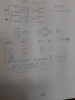
I will do that. Maybe I purchased wrong transformer. I thought it was 24VAC secondaries was required. Will look at BOM again. See attached schematic with +24
Attachments
Last edited:
You get somewhere around input voltage times 1.4 after rectification. Most people are using 18V - 20V secondaries on their transformers for FW amps.
You get somewhere around input voltage times 1.4 after rectification. Most people are using 18V - 20V secondaries on their transformers for FW amps.
Thanks for the information although with the schematic of the aleph j showing 24 volts it would seem most would use what is called out in the schematic. Anyway will look into it and thanks again.
...it would seem most would use what is called out in the schematic.
Take a closer look at the voltage of the transformer secondaries on this schematic.

Yes this schematic shows a transformer with secondary18vac output. This schematic then would not apply to aleph j schematic boards seeking a 24 volt use. Do all pass power supplies ask for 18 volt secondaries for all of the boards? If so I stand corrected. thanks over and out.Take a closer look at the voltage of the transformer secondaries on this schematic.
View attachment 848809
The Aleph J schematic shows +24V and -24V. They are DC voltages. The transformer secondaries output 18VAC which is converted by the power supply to approximately 24VDC.
Sorry for dumb questions; I hope they belong here.
Is the BOM linked on the first post of this thread the current BOM? It looks to be about 7 years old.
I’ve never ordered from Digikey before. Is there a way to order all those parts without having to type them in? Is it possible to upload the list somehow? Any recommendations?
Thanks. I’ve never built anything that wasn’t a full-parts kit before. This is uncharted territory for me. Totally unrelated, but I just built a SpudKit amp (2 tubes). I have nothing to compare it to but it sounds fantastic to me with beat up old Zu speakers. I’m hoping the Aleph J will sound as good or better and have power to drive less efficient speakers.
Hi Alan...I went thru similar processes a few months ago when transitioning from an ACA build to the Pass F5....the BOM has several omissions and one or two modifications so maybe my experience can help. I did gain an enormous amount from people on the Forum and prevailed excessively on 6L6 so I shouldn't encourage you to do likewise
The BOM for the PSU doesn't mention a transformer...the Antek 4220, 400 VA 2 x 20 secondaries works fine, the 18 volt one is recommended but always seems to be out of stock. You will need either a soft start board or thermistors to cushion the switch on surge ( refer to the oldest F5 build guide for instructions on wiring these.) Thermistors are CL60 and you will need 3, the line cap is Vishay BFC 233 820 332 3300pF X2 ( Mouser or DigiKey part number, can't remember which )
Dont fit the Input snubbers at all, and the output snubber is optional. It should be matched to the transformer ( see earlier on in this thread for guidance on doing that ) or you could just use Cx 0.01mF, Cs 0.15mF, R 18 and those values seem to work
I used the PSU in the deluxe chassis to build an F5 and then went on to make it remote to power a BA3...lots of fun. The transition from ACA to the other amps is a bit of a rite of passage but well worth doing
Hi-
I am in the home stretch of My f5T v2 build, and am trying to wrap up some final details. I have two NOS VU meters that I am integrating into the power amplifier case. I am using a cheap VU (stereo) buffer board to allow for calibration and back-light power for the meters. My questions are as follows:
-The driver board requires 12-18 vdc. I have a Hammond torroidal transformer w/ 24vdc @ the secondaries. Can I run an additional wire off the PSU to a terminal block and power the vu buffer board? Obviously I would need to step the voltage down with appropriate resistors. Any concerns with going this route?
-Also, can I simply solder another few wires off the RCA terminals at the amplifier case to provide line level signal for the meters?
I appreciate everyone's help, thanks in advance.
-Wes
- Home
- The diyAudio Store
- V3 Universal Power Supply Circuit Board