18V X 2 X 0.707 - some obvious losses. Roughly. There will be the experts that can give you the full detail.
Download Duncan's PSU Design and Sim app and then you can learn something about it.
Find it here.
I appreciate the reference but I really have no interest in learning about power supply design. I'm just trying to figure out what parts I need to build the power supply that goes into the First Watt F6 and frankly I'm surprised the whole thing is so opaque. 18V x 2 x .707 means nothing to me except that it approximates 24V.
Here‘s a very good read about construction and function of a PSU: Building a Gainclone chip amp power supply.
I appreciate the reference but I really have no interest in learning about power supply design. I'm just trying to figure out what parts I need to build the power supply that goes into the First Watt F6 and frankly I'm surprised the whole thing is so opaque. 18V x 2 x .707 means nothing to me except that it approximates 24V.
OK, maybe 6L6 will be able to help. He has more patience than I do.
In short:
1 X 18V + 18V 300VA or 400VA (prefered) transformer, each secondary feeding one of
2 X 30A rectifier bridges, feeding
1 X V3 DIYAudio PSU PCB, populated with
8 X 15 000 MicroFarad 35V alu electrolytic caps
8 X 0R47 3W resistors
2 X 2K2 to 4K 3W bleeder resistors
2 X 10K or there abouts 1/4W resistors for the LED (not required if LED is not used, and value only affects brightness of LED)
2 X LEDs (not required, only for indicating that PSU is alive)
I think that about sums it up.
Last edited:
I'm just trying to figure out what parts I need to build the power supply that goes into the First Watt F6 .
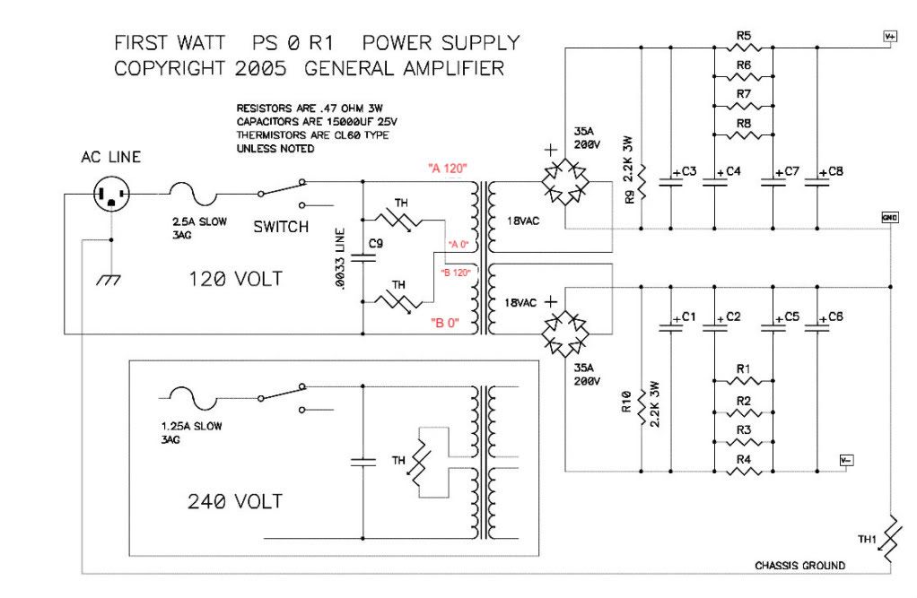
This is the reference schematic.
The chipamp/gainclone PSU link that myleftear posted is absolutely fantastic reference material and explains most everything very nicely. Although there are some practical and specific differences between a gain clone PSU and a Firstwatt, all the information there is worth looking at. You'll have a much better understanding after reading it.

Last edited:
OK, maybe 6L6 will be able to help. He has more patience than I do.
In short:
1 X 18V + 18V 300VA or 400VA (prefered) transformer, each secondary feeding one of
2 X 30A rectifier bridges, feeding
1 X V3 DIYAudio PSU PCB, populated with
8 X 15 000 MicroFarad 35V alu electrolytic caps
8 X 0R47 3W resistors
2 X 2K2 to 4K 3W bleeder resistors
2 X 10K or there abouts 1/4W resistors for the LED (not required if LED is not used, and value only affects brightness of LED)
2 X LEDs (not required, only for indicating that PSU is alive)
I think that about sums it up.
Thank you. One of my sources of confusion is that the Bill of Materials list on the DIY store for the PSU doesn't appear to list rectifier bridges so I'm not clear what brand or part matters there.
Also, the schematic the 6L6 posted includes a thermistor and capacitor before the transformer that also don't appear to be in the BOM. And then the LED's aren't shown in the schematic at all although they are in the BOM.
Hopefully the PCB board makes their location clear.
So I hope you understand my confusion which isn't stemming from laziness LOL.
For rectifier bridges this will be just fine:
https://www.mouser.com/ProductDetai...or/GBPC3502-E4-51?qs=AvlKB63p5SnGQb0LYrYn6w==
The brand does not matter at all. And this 35A bridge will be more than enough to handle the F6.
The LED is not important at all in getting DC to your amp PCBs. The schematic posted by 6L6 is the generic First Watt version. The DIY Audio PSU added the LEDs as a convenience.
For rectifier bridges this will be just fine:
https://www.mouser.com/ProductDetai...or/GBPC3502-E4-51?qs=AvlKB63p5SnGQb0LYrYn6w==
The brand does not matter at all. And this 35A bridge will be more than enough to handle the F6.
The LED is not important at all in getting DC to your amp PCBs. The schematic posted by 6L6 is the generic First Watt version. The DIY Audio PSU added the LEDs as a convenience.
Thanks. 34 week lead time on that part! Hopefully, other rectifier bridges will also be fine now that I know what to look for. I had the same problem with the transformer. I would have liked to have ordered the 400VA version but it is out of stock.
Thank you. One of my sources of confusion is that the Bill of Materials list on the DIY store for the PSU doesn't appear to list rectifier bridges so I'm not clear what brand or part matters there.
A bridge rectifier is just four diodes in a particular configuration. The PSU boards from the store contain two bridge rectifiers, one per channel, comprised of D1-8. These diodes are listed in the BOM. Some people choose to use monolithics instead, you are free to do so, simply snap off the rectifier sections of the PSU boards and discard them, and use monolithics to feed the CRC filter portions. Using monolithics will save you some space, but I'm not knowledgeable enough to get into any of the other pros and cons, I'm pretty new here myself. Hope this helps!
Thanks. 34 week lead time on that part! Hopefully, other rectifier bridges will also be fine now that I know what to look for. I had the same problem with the transformer. I would have liked to have ordered the 400VA version but it is out of stock.
This is the 400V On-Semi version. Even better, just a bit more expensive. But you get the idea. This part is not super crucial as long as it can handle 200V or more and 30A or more, and it realy does not matter who makes it, as long as it is a fairly reputable manufacturer, like On-Semi, Vishay or IXYS.
GBPC3504 ON Semiconductor / Fairchild | Mouser
Last edited:
This is the 400V On-Semi version. Even better, just a bit more expensive. But you get the idea. This part is not super crucial as long as it can handle 200V or more and 30A or more, and it realy does not matter who makes it, as long as it is a fairly reputable manufacturer, like On-Semi, Vishay or IXYS.
GBPC3504 ON Semiconductor / Fairchild | Mouser
Thanks. Does it matter what kind of 15000uF capacitors you use in the power supply. 35mm and 10mm snap in seems to be critical along with 35+VDC but do other things like ripple current or all the other specs make a difference? This one seems like it costs a little more but with slightly better specs? LGY1H153MELC50 Nichicon | Mouser
Nice but not necessary. On paper the better ripple performance is exactly what we want. That the two components will produce audible differences is unlikely, based on my limited research. That being said, I personally spent the extra.
Thanks. Does it matter what kind of 15000uF capacitors you use in the power supply. 35mm and 10mm snap in seems to be critical along with 35+VDC but do other things like ripple current or all the other specs make a difference? This one seems like it costs a little more but with slightly better specs? LGY1H153MELC50 Nichicon | Mouser
That one is fine. In general the ones with the better ripple current is better for smoothing.
Preferred electrolytic power supply capacitor specs:
- high maximum operating temperature, for longer life
- high life (hours)
- high ripple current capacity - for lower temperature increase during operation, therefore longer life
- rated voltage higher than actual voltage at capacitor, for longer life
It's a compromise between price and performance.
If your amplifier case is well ventilated and the operating temperature inside the case is kept near ambient temperature, and the temperature is not near the maximum operating temperature of the capacitor, then it is less of an issue and the capacitors will last a long time. If the temperature inside the case is high relative to ambient and closer to the maximum operating temperature of the capacitor, then the life of the capacitors will be shortened.
Last edited:
Ben,
The lifetime as specified is when the cap is operated at the temp-limit?
And is doubled when temperature is halved, more or less?
The lifetime as specified is when the cap is operated at the temp-limit?
And is doubled when temperature is halved, more or less?
I just did some Googling and there is quite a lot of information on the net.
Some information:
Electrolytic capacitors determine the lifetime of a power supply | XP Power
Calculating the Lifespan of Electrolytic Capacitors with De-Rating - News
https://www.mouser.com/pdfdocs/ELNAReliabilityAlumElecCaps.pdf
Some information:
Electrolytic capacitors determine the lifetime of a power supply | XP Power
Calculating the Lifespan of Electrolytic Capacitors with De-Rating - News
https://www.mouser.com/pdfdocs/ELNAReliabilityAlumElecCaps.pdf
Wow, thanks, ben!
I thought you could just pop that into the keyboard, and here we are with topnotch info! [emoji2956]
I thought you could just pop that into the keyboard, and here we are with topnotch info! [emoji2956]
I'm about to finalize my order of parts for the F5/F6 Power Supply Unit. I think I've mostly figured out what to get but I still had two questions.
The schematic for the PSU that 6L6 shared shows a couple of thermistors and a capacitor on the input side of the transformer. I have no idea what those are or what values they should be or if they are even part of the circuit I am building?
Likewise, the Bill of Materials on the DIYStore for the PSU includes a number of input and output snubber capacitors and resistors. I haven't been able to figure out what those are or whether I need them. If I buy two Bridge Rectifiers can I just ignore the input snubber resistors and capacitors or are they still needed?
Thanks.
Thank you. One of my sources of confusion is that the Bill of Materials list on the DIY store for the PSU doesn't appear to list rectifier bridges so I'm not clear what brand or part matters there.
Also, the schematic the 6L6 posted includes a thermistor and capacitor before the transformer that also don't appear to be in the BOM. And then the LED's aren't shown in the schematic at all although they are in the BOM.
Hopefully the PCB board makes their location clear.
So I hope you understand my confusion which isn't stemming from laziness LOL.
I'm about to finalize my order of parts for the F5/F6 Power Supply Unit. I think I've mostly figured out what to get but I still had two questions.
The schematic for the PSU that 6L6 shared shows a couple of thermistors and a capacitor on the input side of the transformer. I have no idea what those are or what values they should be or if they are even part of the circuit I am building?
Likewise, the Bill of Materials on the DIYStore for the PSU includes a number of input and output snubber capacitors and resistors. I haven't been able to figure out what those are or whether I need them. If I buy two Bridge Rectifiers can I just ignore the input snubber resistors and capacitors or are they still needed?
Thanks.
CL60s are commonly used for the thermistor(s) in these builds. These particular thermistors on the AC inputs are to smooth out the spike of inrush current that happens when you first turn on the amplifier. All these big ole capacitors we've been talking on, they go from 0-100 as quick as they can, all at once, taking a big gulp of current in the process. Depending on your wiring this may even be big enough to flip a breaker. The thermistor is a temperature-variable resistor. Try thinking of it like a potentiometer, but the position of the knob is set by temperature instead of your fingers. Maximum resistance happens at lower temperatures, so at room temp you are getting basically full resistance. If you pass a bunch of current through this resistor, it will start heating up. As the thermistor heats up, the resistance drops. So after inrush, it should be hot enough to be basically full-open, and stay open as long as the amplifier stays on.
The input capacitor is a safety cap, you can read about them here, in the Basics section. I picked up a few different XY caps recently but I think the one I'll be using for my F5 build is a Vishay AY1332M57Y5UC63L0.
It's my understanding that the snubbers are optional, and I was advised to first build and test my PSUs without them, only adding them to solve certain problems that may arise. I don't know much more beyond this, as I'm also pretty new to all of this.
If you bought two bridge rectifiers you can ignore every component on the diode portions of the PSU PCBs, they are unrelated to the snubbers or any of the other components we've just discussed.
Last edited:
- Home
- The diyAudio Store
- V3 Universal Power Supply Circuit Board