Can you 'breadboard' a version that has the Cap Mx on the output rather than the reg chip? Teddy Pardo found this works better in his early regulator designs some years ago - and using electro caps back then too, not tants.
Hi Project16
Could you please be more specific in regard to the sonic differences between the 2 PS?
"What" are the flagrant benefits to your ears? Always interested in your feedback
Thanks
Claude
Could you please be more specific in regard to the sonic differences between the 2 PS?
"What" are the flagrant benefits to your ears? Always interested in your feedback
Thanks
Claude
Hi Ernst
I once tried the « EUVL approach « for jfet as input but has not noticed a special sound difference. Also not so easy to “match” the so “complementary” jfet pair...
For the USSA amp, yes you have to connect both ground to PSU. See sketch below.
Fab
Hi Fab, thanks for the advise. I somehow was confused by Ground and Powerground until I checked the circuit again. For whatever reason I was thinking, the GND pin was for the speaker and the PGND was going to the psu. So now it is clear. With both connected to the PSU GND everything is doing well 🙂
Musiiiiic
So - today my USSA5 played for the very fist time musiiiiiiiiiic 🙂
Not yet in my system but on my Whammy HPA with some very old Fostex FE103 plain chassis - suboptimal, but the dynamic potential of this amp showed up. I have it running on 0,95 A, one 400VA trafo, two cap multiplier boards in a very small amp chassis. Cabling could be improved, but I'll put in my system soon after run in for a few hours. Me very happy! The USSPA has been almost finished. Before it can make musik I have to wait for the right heat sinks. Mine are to high for preamp box. So in a few days it might happen.....
Cheers
Ernst
Hi James, this is my plan. Will install a babysitter underneath, even if the 3U300 chassis seems big enough for 90 w dissipation.
Cheers
Ernst
Cheers
Ernst
Progress Update
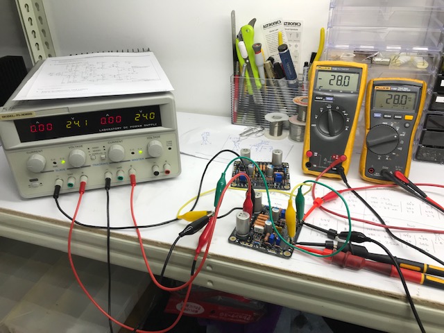
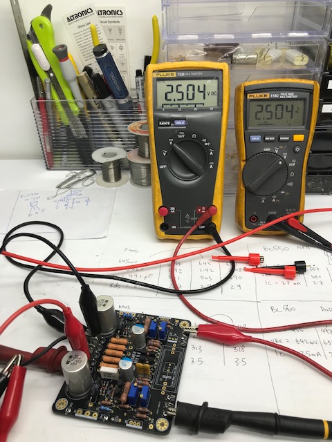
I received a bag of parts yesterday and carried on with my build.
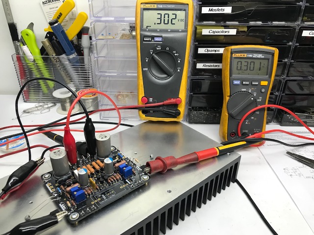
Using a 24VDC psu, the current source adjustment was easy to dial-in and very stable at 28 mV. Nice to have a detailed build manual. 🙂 Thanks Fab.
The input stage current adjustment went well too, a little more sensitive to adjust but I managed to get 2.5 VDC +/- about 5mV - a good result and strangely satisfying for some part of my mind...
Next task is some transistor Vgs checks and a bit of tracing, largely for my own education.
Here is a snap of my progress so far.
I received a bag of parts yesterday and carried on with my build.
Using a 24VDC psu, the current source adjustment was easy to dial-in and very stable at 28 mV. Nice to have a detailed build manual. 🙂 Thanks Fab.
The input stage current adjustment went well too, a little more sensitive to adjust but I managed to get 2.5 VDC +/- about 5mV - a good result and strangely satisfying for some part of my mind...
Next task is some transistor Vgs checks and a bit of tracing, largely for my own education.
Here is a snap of my progress so far.
Attachments
I am glad you appreciate the manual I put a lot of time to write it. It is a good start Johnny Canuck. Keep us posted on your next progress.
Fab
Fab

Hello Fab,
I am little confused between schematic in the manual and the board. I am not sure this has been already answered.
The board has GND, PGND and GC. The schematic shows only GC and GP. The GP in schematic seems like the PGND on the board. According to schematic, R27 sits between GC and GP. On the board, the R27 sits between GC and GND.
Can you please clarify and tell me how we should connect the PGND and GND in final circuit?
Thanks
Balaji
For a short while I have given away my hi efficient Bastanis speaker, which are easy to drive and I put an old pair of Tannoys in our living room. It's a SRM10B, an 8 inch dual concentric monitor speaker, 35 years old I guess, but with mint NOS drivers. They are not easy to drive and they need power. The USSA5 has enough for them. It is an absolute pleasure listening to them. Powerful, dynamic holographic. Of course boxy compared to the Bastanis open baffles but otherwise really good. Great Amp Fab! Thank you!
Cheers, Ernst
Cheers, Ernst
Last edited:
Sorry off topic, my pic hosting site only limits 2 pics, i got more to share.
Can anyone recommend me another more reliable picture hosting site ?
Thanks
Can anyone recommend me another more reliable picture hosting site ?
Thanks
Hello BalajiHello Fab,
I am little confused between schematic in the manual and the board. I am not sure this has been already answered.
The board has GND, PGND and GC. The schematic shows only GC and GP. The GP in schematic seems like the PGND on the board. According to schematic, R27 sits between GC and GP. On the board, the R27 sits between GC and GND.
Can you please clarify and tell me how we should connect the PGND and GND in final circuit?
Thanks
Balaji
See post #638.
Fab
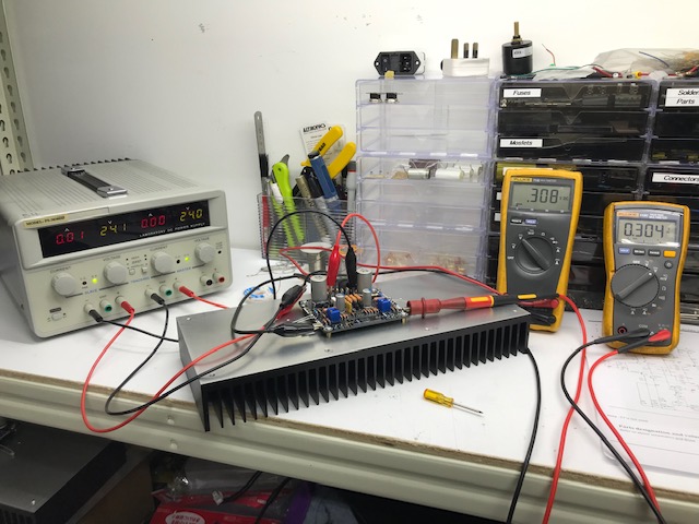
As per last picture, all ok until i install the Mosfets.
Got into some issue at Step 8.17...
Manual says fine tune output for less than 5mV, but no matter how i adjust P1 & P2, both channels got -5 'ish V and -18 'sh Volts. The Mosfets doesn't appears to be shorted because it response gradually when i tweak P1&P2.
Did anyone experience these ?
Got into some issue at Step 8.17...
Manual says fine tune output for less than 5mV, but no matter how i adjust P1 & P2, both channels got -5 'ish V and -18 'sh Volts. The Mosfets doesn't appears to be shorted because it response gradually when i tweak P1&P2.
Did anyone experience these ?
The above speaker output voltage are with respect to PGND.
However, if i measure speaker output terminal with respect to GND tab, I can achieve less than 5mV readings.
Briefly touch my finger at the input terminal, the multimeter register some AC voltage swings. I think my amp is working, but the PGND and GND tabs confuses me now.
Just sharing...
However, if i measure speaker output terminal with respect to GND tab, I can achieve less than 5mV readings.
Briefly touch my finger at the input terminal, the multimeter register some AC voltage swings. I think my amp is working, but the PGND and GND tabs confuses me now.
Just sharing...
- Home
- Amplifiers
- Solid State
- USSA-5 Build with Review