I guess I was confused between this one and what the user in Post #129 did. Did his testing occur before the offering shown in your link?
Tony,
The puck presented here http://www.diyaudio.com/forums/digi...killer-high-end-transport-13.html#post3416072 was reviewed by customer here http://www.diyaudio.com/forums/digi...killer-high-end-transport-13.html#post3420613
This is the last CD puck I made and I think that his shape, height and finish is good enough to be compared with the best ones.
As I´m a perfectionist, there will be always a better next one. 🙂
Hope I´m clear now.
Regards,
Tibi
Last edited by a moderator:
PS combination
Tibi, is this power supply combination possible?
Separate +5V feed for the clock
Rest of the PCB fed from the main +8V power supply board
Tibi, is this power supply combination possible?
Separate +5V feed for the clock
Rest of the PCB fed from the main +8V power supply board
Tibi, is this power supply combination possible?
Separate +5V feed for the clock
Rest of the PCB fed from the main +8V power supply board
Yep. It is possible and very recommended.
Regards,
Tibi
Hi Tibi,
Thank you for the very generous offer for the new puck.
I just forwarded you a payment with Paypall as requested, but I could not put a note, this was for the new puck.
So I needed to inform you.
Thank you truly,
Jean-Charles
Thank you for the very generous offer for the new puck.
I just forwarded you a payment with Paypall as requested, but I could not put a note, this was for the new puck.
So I needed to inform you.
Thank you truly,
Jean-Charles
Yep. It is possible and very recommended.
Regards,
Tibi
How would one do this? I looked at the schematic and couldn't see which bead(s) to remove to make a separate +5V for the clock but keep the rest of the voltage feed intact.
Is a separate +5V for the clock significantly better than a +8V feeding the mechanism only, and separate +5V for the rest of the board (including clock)? In all cases the +8V and +5V would be fed by separate transformers.
Hi Tibi,
Thank you for the very generous offer for the new puck.
I just forwarded you a payment with Paypall as requested, but I could not put a note, this was for the new puck.
So I needed to inform you.
Thank you truly,
Jean-Charles
Thank You, Jean-Charles !
Regards,
Tibi
How would one do this? I looked at the schematic and couldn't see which bead(s) to remove to make a separate +5V for the clock but keep the rest of the voltage feed intact.
Is a separate +5V for the clock significantly better than a +8V feeding the mechanism only, and separate +5V for the rest of the board (including clock)? In all cases the +8V and +5V would be fed by separate transformers.
Remove L8 and use L8 PCB pad to feed +5V directly to oscillator can.
Try one by one. First power clock from a separate PS, than feed laser and ASP section with a better PS. Later on you can try also separate 8V for servo and 5V for DSP.
There are other many combinations and is up to you to try them all. 😀
Regards,
Tibi
You're no help! 🙂🙂🙂
I'm hoping that for my first attempt, separating out the 8V for the transport/servo and feeding the DSP and clock from the same 5V would be a better solution. I'm thinking getting anything having to do with the servo and motors away from the digital audio circuits is probably the best first step.
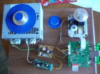
The second PSU is a 5V reg, based on Martin's
Using 3-pin regulators off-piste: part 4
It is for the separate 5V supply. You can see it soldered to one of L4's (removed) pads that is connected to L5. Ground is soldered to neaby ground plane. Another convenient 5V soldering pad is the V4 test point. FWIW, there are 2 9-0-9 transformers in the ATX PS case.
Cheers,
For my custom model I'd like to use a power entry connector with a built in switch. The idea is that switch will control the power to the digital circuitry, besically keeping that on all the time. A second switch on the front panel will control power to the mechanism motors and the display. My experience tells me keeping the digital stuff cooking all the time makes for better sound.
What is the feeling on using a power inlet with built in filtering? Something like this
15CUFE1 - TE CONNECTIVITY / CORCOM - POWER ENTRY MODULE, MALE, 15A | Newark
What is the feeling on using a power inlet with built in filtering? Something like this
15CUFE1 - TE CONNECTIVITY / CORCOM - POWER ENTRY MODULE, MALE, 15A | Newark
I ve been using schafner ones for quite some time with excellent results. The one that has dual everything, including fuses.
FN389B-6-21 Schaffner | Mouser
FN389B-6-21 Schaffner | Mouser
Mmm, looks nice.
I wonder if using a regular inlet and hanging a really good cap like a Mundorf or V-Cap on the primary side would be better.
I wonder if using a regular inlet and hanging a really good cap like a Mundorf or V-Cap on the primary side would be better.
Tibi, with respect to my plan of having separate 8V and 5V supplies, does the 8V feed anything besides the mechanism? I'm trying to decide if I want to keep the 8V and 5V powered on all the time, and add a switch for the display only, or add that "run time" switch for the entire 8V feed and display. If the 8V does not power anything on the main PCB that "needs" to be on all the time then I'd make that part of the switch to throw when wanting to play a CD.
Tony,
8V power directly only LA6541.
Regards,
Tibi
Thanks Tibi. I guess then it will be okay to keep the 8V feed as separately switched, but I think I will do it at the 8V output of the PS board, and not at the AC input. That way at least the PS will remain at a quiescent operational state.
- Home
- Source & Line
- Digital Source
- Using the new 2012 Shigaclone to create a killer high end transport