Tibi, not sure if I can track down an ESR meter. With regard to your method, however, shouldn't the use of the resistors not be needed if I have a constant current power supply? That's really all the resistors are doing in this case - insuring a small current to the caps during the forming process.
Tibi, not sure if I can track down an ESR meter. With regard to your method, however, shouldn't the use of the resistors not be needed if I have a constant current power supply? That's really all the resistors are doing in this case - insuring a small current to the caps during the forming process.
In fact resistor will act like a variable ccs. While the voltage is dropping the current will drop as well protecting the cap from overheating.
Regards,
Tibi
Tibi
Can you please clarify how to split and where to power the various sections, motor 8.3v, digital 5v, and TentLabs oscillator If using "bobken" regulator for the digital section and a "pinkfish flea for the TentLabs oscillator?
Can you please clarify how to split and where to power the various sections, motor 8.3v, digital 5v, and TentLabs oscillator If using "bobken" regulator for the digital section and a "pinkfish flea for the TentLabs oscillator?
APK,
Document was updated to include these descriptions, version 1.6 - see page 8
https://docs.google.com/document/d/1vlabZc_1If3x12ox2A5ECZxC0HLGnuOWdM-j9X4b7Q0/edit#
Regards,
Tibi
Document was updated to include these descriptions, version 1.6 - see page 8
https://docs.google.com/document/d/1vlabZc_1If3x12ox2A5ECZxC0HLGnuOWdM-j9X4b7Q0/edit#
Regards,
Tibi
In fact resistor will act like a variable ccs. While the voltage is dropping the current will drop as well protecting the cap from overheating.
Regards,
Tibi
I have the power supply and will be doing the cap forming maybe tonight or tomorrow. The HP supply is a variable DC supply that can be set for constant voltage / constant current, but I'm not sure that's what I want to do.
I was thinking of setting up a cap with the 100KOhm resistor in series and then ramping up the voltage slowly until I get to 50 VDC. Or should I just set the voltage to 50 VDC, turn off the supply, hook everything up, and turn it back on?
Set the voltage to 50V and let the cap to draw needed current trough 100K resistor.
Regards,
Tibi
Regards,
Tibi
APK,
Document was updated to include these descriptions, version 1.6 - see page 8
https://docs.google.com/document/d/1vlabZc_1If3x12ox2A5ECZxC0HLGnuOWdM-j9X4b7Q0/edit#
Regards,
Tibi
Ι ve been trying to see how to upgrade the psu parts.
Where would you reckon would be the best place to ground the separate Vs?
Which V powers the motor driver?
Thanks again
Ι ve been trying to see how to upgrade the psu parts.
Where would you reckon would be the best place to ground the separate Vs?
Which V powers the motor driver?
Thanks again
Dimkasta,
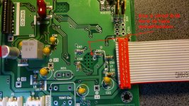
For separate Vs best place to ground is main board ground input - connector J5 Dout GND.
Motor driver need 8V. J6 connector is 8V. 🙂
Regards,
Tibi
Thanks a lot for the quick answer
So motors still get power from J6 if we use separate V1,V2,V3,V4 ?
Do you mind posting what voltages/amperages are needed for each Vx?
So motors still get power from J6 if we use separate V1,V2,V3,V4 ?
Do you mind posting what voltages/amperages are needed for each Vx?
Thanks a lot for the quick answer
So motors still get power from J6 if we use separate V1,V2,V3,V4 ?
Do you mind posting what voltages/amperages are needed for each Vx?
V1=V2=V3=V4=5V
For V1 current should be between 30mA and 60mA or more depending on disk type (CD,CD-R or CD-RW) and speed. An 150mA should be enough.
For V2 current is ~40mA. An 5V at 100mA should cover the need.
For V3 current is ~20mA or less. 50mA should be OK.
For V4 current is ~ 50mA. 100mA should be OK.
Regards,
Tibi
Last edited by a moderator:
In fact resistor will act like a variable ccs. While the voltage is dropping the current will drop as well protecting the cap from overheating.
Regards,
Tibi
I just bought a Blue ESR meter! Hope to have it by Saturday. Better safe than sorry. I want to show progress as quickly as possible Tibi 😉, but apart from the two Shigas on my plate I'm also trying to finish mods to my (vinyl) turntable and completing the construction of a constrained layer platform for same.
dimkasta
Are you powering the 5v with 4 separate supplies or removing just L4 and powering all the 5v sections with one supply?
Tony
Are you powering the 5v with 4 separate supplies or removing just L4 and powering all the 5v sections with one supply?
Tony
dimkasta
or removing just L4 and powering all the 5v sections with one supply?
Tony
I don t think that is possible. Tibi's manual states that if we use separate V4, we have to use separate V1,V2 and V3 too.
Tibi? can you shed some more light please? 😀
Last edited:
Well there are many other combinations as well. It´s up to your imagination how to combine them.
If you want to use separate 5V supply for V4, you need to remove L4 & L5 beads. Than, you can power the rest of Shiga via a separate 5V for V3 without removing L1, L2 & L3 beads.
Main 8V should be present as well via J6.
Hope is clear. 🙂
Regards,
Tibi
If you want to use separate 5V supply for V4, you need to remove L4 & L5 beads. Than, you can power the rest of Shiga via a separate 5V for V3 without removing L1, L2 & L3 beads.
Main 8V should be present as well via J6.
Hope is clear. 🙂
Regards,
Tibi
Tibi, what is the result on the display when this is done? Is it necessary for the boards which had the contrast mod update you already did?
- Home
- Source & Line
- Digital Source
- Using the new 2012 Shigaclone to create a killer high end transport