Yes that's how i did it, the controlcircuit floats and is powered at the load only.
So the patchcap has to be as small as possible ?
I will let you know if the sound is restored and that it's hopefully nicer than without sense wiring.
If necessary (with purpose made layout on a V1 it is not), it better be smallest sufficient value to kill the oscillation. If marginal, it can also be detected subjectively by being smooth on normal program but hardening when there is busy and transient content. Especially in the highs. Then you add a bit more if you went too low. I suppose scope and FFT are not available.
only the 2 cheap scopes attached to my head. I didn't like the sound with the oscillating hypno at all. Harsh, compressed, well I do know what i like and the basic Hypno was great so I have something to compare with.
Goodnight.
Goodnight.
Start with the 200pF that stopped the electrical tell tale oscillation clues, listen, then see if 100pF still stops the electrical clues and if any better, dare lower if it shows a good trend etc. Goodnight and let us know. I wish success and final mounted regs and ONO pics.
acidbrain and salas: I thought that sense wiring should be the same gauge as the force wiring? otherwise would it not sense the incorrect voltage drop? it appears in your build acidbrain that they are not just different, but completely different.
Sense can be thin, carries very little current. Corrects for the force, ideally it could be thin too since corrected, but we don't want to do large corrections since there is finite bandwidth due to cable nH and inherent error amp BW, so we keep force in logical gauge.
but I thought the whole idea of sense was that it mimicked the voltage drop present in force as part of sensing the voltage drop? otherwise at a thinner gauge would it not drop more voltage than force and therefor not sense the correct voltage at the load? or is this irrelevant as long as its sized to handle the correct and lower CURRENT at the desired voltage?
Last edited:
The sense wires feed a signal difference to a measuring bridge.
The bridge sends an error correction voltage to the control circuit.
The resistance of the sense wires has virtually no effect on the size of the error correction voltage.
Measure your output voltage.
Add 1r0 to each sense wire.
Re-measure the output voltage.
Replace the 1r0 with 10r0 in the sense wires.
Re-measure the output voltage.
If your operating conditions for all three measurements are kept the same I don't think your will be able to measure any difference in output voltage.
Admittedly this is a DC check, but added resistance will have the same error measuring effect at AC frequencies.
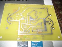
Salas v1.0 4 wire shunt reg PCB PS2.1 REV. B
Hey guys and gals,
After many months of on/and/off DIY-ing (as life and marriage and job have their demands), sending versions out to the prototyper (and to myself to work and back home and then to work and then back home, all this manic behavior by email...), dealing with DIY friends never happy with what they're getting from the kindest bottom of my heart - you know who you are!!! - and so on and so forth, I finally got this done!
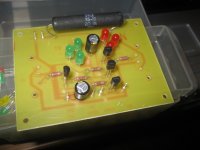
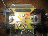
Salas V1.0 4 Wire Shunt Reg - religiously respected the guru's designation - is done and ready. If I ever get to upload the pictures to this post, you'll also see her beauty in all its splendor.
It absolutely worked plug and play, although some fine tuning of the Vref to get the 7.1V out I need is still outstanding. Maybe I'll get that blue LED in want in there... Awesome.
It definitely is available to anybody that wants it, as soon as I get the production scheme (therefore pricing) in order.
Some features:
- the heftiest individual TO-247 heatsinks I could find (Aavid Thermalloy 6400BG);
- remote sensing outputs, featured with solder jumper trace islands, to be easily shorted if those O/Ps are not to be used;
- power resistor is intended to be Mills (per spec'd dims), and electrolytics are to be Elna Cerafine, although Panny FMs will fit OK (5mm types, FMs are like 3.5mm or about there);
- it's definitely intended to be a versatile Salas Shunt PCB, with no rectifiers/filtering caps etc. on this PCB (although I lined up also some PCBs for that), but only the regulating stages (CCS, Vref, comparator and current sink etc.); the HS can do pretty hefty currents as the tracing, there are plenty locations for LEDs for different combinations for desired Vref, the heat distribution scheme is faily homogeneous (see the location of HSs and power resistor), so this could withstand some serious use.
I am putting together a writeup with some maximum ratings.
Please let me know what you guys think. I haven't posted here much lately, but some pretty sustained work has been laid onto this and many thanks to Salas who helped greatly, as all of you know him... I can't say how excited I am to see this baby breathing.
Best,
aR.
Hey guys and gals,
After many months of on/and/off DIY-ing (as life and marriage and job have their demands), sending versions out to the prototyper (and to myself to work and back home and then to work and then back home, all this manic behavior by email...), dealing with DIY friends never happy with what they're getting from the kindest bottom of my heart - you know who you are!!! - and so on and so forth, I finally got this done!
Salas V1.0 4 Wire Shunt Reg - religiously respected the guru's designation - is done and ready. If I ever get to upload the pictures to this post, you'll also see her beauty in all its splendor.
It absolutely worked plug and play, although some fine tuning of the Vref to get the 7.1V out I need is still outstanding. Maybe I'll get that blue LED in want in there... Awesome.
It definitely is available to anybody that wants it, as soon as I get the production scheme (therefore pricing) in order.
Some features:
- the heftiest individual TO-247 heatsinks I could find (Aavid Thermalloy 6400BG);
- remote sensing outputs, featured with solder jumper trace islands, to be easily shorted if those O/Ps are not to be used;
- power resistor is intended to be Mills (per spec'd dims), and electrolytics are to be Elna Cerafine, although Panny FMs will fit OK (5mm types, FMs are like 3.5mm or about there);
- it's definitely intended to be a versatile Salas Shunt PCB, with no rectifiers/filtering caps etc. on this PCB (although I lined up also some PCBs for that), but only the regulating stages (CCS, Vref, comparator and current sink etc.); the HS can do pretty hefty currents as the tracing, there are plenty locations for LEDs for different combinations for desired Vref, the heat distribution scheme is faily homogeneous (see the location of HSs and power resistor), so this could withstand some serious use.
I am putting together a writeup with some maximum ratings.
Please let me know what you guys think. I haven't posted here much lately, but some pretty sustained work has been laid onto this and many thanks to Salas who helped greatly, as all of you know him... I can't say how excited I am to see this baby breathing.
Best,
aR.
Attachments
Will the circuitboard be smaller? More compact?
Since we pay for the area, but most important is prformance and the fact that we will stuff maybe 5 of those boards in a aready built Blue Ray player for instance.. not much room left 🙂
Otherwise it looks great!
Since we pay for the area, but most important is prformance and the fact that we will stuff maybe 5 of those boards in a aready built Blue Ray player for instance.. not much room left 🙂
Otherwise it looks great!
esl 63,
I understand where you're coming from. This, as designed right now, is intended to handle higher currents, up to like 3A, reason for the hefty heatsinks.
In order to miniaturize this and make it more adequate to lower currents / smaller spaces, I'd need to compact it overall somewhat (possible due to lower temperature values and gradients overall), and at the same time put some smaller heatsinks on there (either height-wise, or also footprint-wise). What would be your specifications? i.e.: O/T current and voltage, ballpark values.
I am currently investigating sending this (the finished and built board) to a more professional PCB manufacturer (solder masking, silkscreening). But: I could also possibly redesign this and send it back to my small single-run-production PCB maker... I am not sure yet.
Let me know what your requirements are. I am trying to get an idea of heat dissipation needs etc.
Cheers,
aR.
PS
...when I say "redesign this," I mean make a second version for lower power requirements.
aR
...when I say "redesign this," I mean make a second version for lower power requirements.
aR
Vref
Salas and all,
I have some questions on this.
1. How do you feel about Vref being given only by a resistor (by grace of the CCS operation, certainly)? I believe QHs version of this does that, but I want to hear your position on it. In my case, I need 7.1V out, which with the Idss of the respective 2SK170BL I have in there (6.4mA) is given almost exactly by a 1kohm resistor placed instead of all of the LEDs.
I am thinking of possibly providing the option of putting in Vref position a fixed R in series with a trim pot for adjusting the Vout, while leaving the LEDs eyelets in place. C1 still needed in that case?
2. What parts would better go in place of the IRFP9240 for a lower power application?
Thanks all!
Best - Rax.
1. Leds only are better than resistor if you can help it. Fixed resistor is better than trimmer if you want to keep some Leds and add more drop to the chain by substituting a resistor for an LED. Capacitors remain as they are.
2. IRF95xx & IRF96xx series are adequate TO-220s. The shunt (across rails) one must have analogous ygfs to IRFP9240, the CCS part can be faster i.e. less Ciss, Crss and its ygfs is not of prime concern. You can try 9520,9540,9620,9640. xx20 for CCS. If you test it stable will be OK. Don't run more than 10-15W on a TO-220.
2. IRF95xx & IRF96xx series are adequate TO-220s. The shunt (across rails) one must have analogous ygfs to IRFP9240, the CCS part can be faster i.e. less Ciss, Crss and its ygfs is not of prime concern. You can try 9520,9540,9620,9640. xx20 for CCS. If you test it stable will be OK. Don't run more than 10-15W on a TO-220.
Hi,
the IRF540 is a 28A, 150W, 175degC device in a To220 package.
It can manage 30W dissipation and needs to be de-rated to 84W when fitted to a 1C/W heatsink. This is based on Ta=35degC, Ts=65degC, Tc=80degC, Tj=110degC.
In other words when running at Tj=110degC it has a capability of 84W and is dissipating only 30W. That's a good factor of safety.
I might even risk 50W dissipation for medium term worst case conditions. Note that Ta will be rising quite quickly when mains supply voltage is at maximum tolerance.
The IRFP9240 is a 12A, 150W, 150degC device in a To247 package.
EDIT.
I have just done a 50W worst case dissipation. If Ta rises to 50degC, then the de-rating brings the FET down to 50W. i.e International Rectifier guarantee that most of their devices will survive without damage when dissipating 50W at Tc=125degC. I would accept that for the short time that the UK mains supply will stay up at 254Vac.
Last edited:
Salas,
You argue that LEDs are better than pure resistor in Vref duty - what are you grounding that on?
Is it because the LEDs, as opposed to resistor, do perform as voltage references relatively independent of the rest of the circuit, while resistors basically need a CCS in series to do that? Therefore, overall, neding a simpler implementation to do Vref duty, therefore "better."
I am asking this because my paramount concern in a Vref is self-generated noise, and in that department I don't know anything better than pure resistor (well, some of them, like bulk foil etc.).
I know you also indicated a while ago that you are a fan of LEDs as voltage references beacuse of very little noise generated, by your own measurements. Do you have some hard data on that? Possibly some references, articles, etc?
Thank you much.
aR
Hi,
yes, an LED is a good Voltage reference when it is fed with a constant current.
It is good because it has low noise. It is good because once over the knee in it's Vf vs If characteristic it behaves as a resistor many times lower than a plain resistor passing that current.
For higher voltage duty where a string of 10LEDs generating ~18V would be equivalent to 3k0 passing 6mA, the LEDs will be of significantly lower impedance. I think the LEDs will also be quieter.
I would always use at least one LED in SALAS shunt as an indicator and for higher voltages than can conveniently be achieved with a string of LEDs add a location for a variable resistor to fine tune the output voltage and a Zener//cap for the big voltage.
EDIT.
I have just done a 50W worst case dissipation. If Ta rises to 50degC, then the de-rating brings the FET down to 50W. i.e International Rectifier guarantee that most of their devices will survive without damage when dissipating 50W at Tc=125degC. I would accept that for the short time that the UK mains supply will stay up at 254Vac.
Because its constant current I feel better using at 1/3 50W. That is why I said no more than 15W constantly for long life no worries. YMMV of course.
- Status
- Not open for further replies.
- Home
- Amplifiers
- Power Supplies
- Using the HYPNOTIZE as a general shunt reg PCB