I would use completely different power sources for different stuff, but if its needed to tap off due to space and economy, shunt reg lends best for minimum intermodulation. Just tap the main rails and rev up the available current according to your extra consumptions. If you have unequal needs for rails, differentiate the resistors so to leave equal residual current in the regs.
After having very good results (fast/clean) by hooking up my ONO phono to Hypnotize shunt I tried to use sense wiring. That didn't went well, I heard some noise coming from the shunt, the output voltage dropped from 30+ to 20V. Not connected the voltage was okay. I restored the voltage by adding another 100uF elco on the place were sense & load wiring meet.
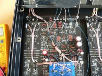
Initial foundings :
the 2 delay relais didn't switch at the same time and the sink from one "-" pole of the shunt got hotter than before. The sound was slow and grainy. Slow because of the Extra 100uF and I think that the voltages from the shunts are not stable and having distortion.
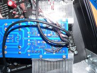
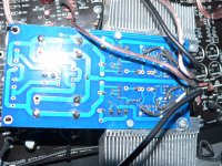
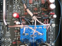
You can see the 2 coax wires. left is - and right is +, those 2 little Elna's were added to get the output stable. + and - sense are connected at the load were they meet with the power + and -. Sense grounds are connected to the so called star earth = incoming 0 + input 0 + shunt 0 + sense 0.
I can't find out what I did wrong and the rebuilding of the Hypno did cost me a lot of time, I would rather fix this than go back to standard shunt.
If anyone can put a light on this that would be great 🙂
Regards, Erik.
Initial foundings :
the 2 delay relais didn't switch at the same time and the sink from one "-" pole of the shunt got hotter than before. The sound was slow and grainy. Slow because of the Extra 100uF and I think that the voltages from the shunts are not stable and having distortion.
You can see the 2 coax wires. left is - and right is +, those 2 little Elna's were added to get the output stable. + and - sense are connected at the load were they meet with the power + and -. Sense grounds are connected to the so called star earth = incoming 0 + input 0 + shunt 0 + sense 0.
I can't find out what I did wrong and the rebuilding of the Hypno did cost me a lot of time, I would rather fix this than go back to standard shunt.
If anyone can put a light on this that would be great 🙂
Regards, Erik.
Attachments
Last edited:
Those layouts are not made for sense wiring. Provided you did hack correctly for the 4 wire connections, your results show sure oscillation. One thing that I would try is to attach force ground output exactly on output capacitor's (-) and not elsewhere. If that does not help, maybe 100pF from collector to base of each rail's BC550/560 could tame the oscillation. Even if that would not work, I would restore the connections to original and forget about converting it.
I did mod it the right way and will try out your suggestions.
It's a learning stage and the advantage against the standard onboard powersupply is huge. Thanks Salas.
It's a learning stage and the advantage against the standard onboard powersupply is huge. Thanks Salas.
It's a learning stage and the advantage against the standard onboard powersupply is huge.
Did i see it right, you are using Dragan's boards and are comparing it to his standard PSU?!!
Experience ist most welcome, perhaps better by PM not to be too off-topic. My Dragan Boards are waiting, too.
cu
difool
LOL Difool, yes use Dragan's external powersupply and use the Hypnotize for internal power. The difference is there, I also changed the MC stage (thanks Salas !) so there is no cascode or 2 caps in the way of the signal. PM me for more off-topic findings 🙂
The sense must return to no star by the way. The force only returns. The sense sort of ''hangs'' the error amp control circuit grasping the force lines only where they meet the load.
Maybe I took the schematic too literally. I disconnected the +/0 and 0/ - steering part, coaxed them, + inner wire, 0 shield, - inner wire, 0 shield. + and - to meet force load, shields go apart to star load. So,if the sense shield don't go back, were is it connected to the 0 so the control circuit gets power ?

Salas, the only difference I see is that the shields don't go to star earth but go directly to the load. So is it better to get rid of the star earth, connect shields seperate and directly on the load as possible + connect inputvoltage 0 directly to 0 on the hypno ?
This is better brain training than sudoku 🙂
I'm using a floating earth.
This is better brain training than sudoku 🙂
I'm using a floating earth.
Its not a simple difference. Its important. Try to follow the lines as on the diagram projecting that logic on the board hack.
I tried 200pF for the bc550/560 and the voltage is instantly restored and with quiet Hypno's. 🙂
Tomorrow I will hear it out, looks good for now !
Tomorrow I will hear it out, looks good for now !
Did you rearrange the sense/force cabling connections also? I know I recommended you the capacitors patch, but if the oscillation is attributed to cabling and can be had clean without patching, the performance can be even better. Remember the sense shield does not return to a common reg's point with force shield. They only meet at load's 0. Force shield only returns to reg's 0, which is also common to its input 0.
It's difficult Salas, The ONO has no star earth or load earth, just one 0 that goes everywere (power 0 = signal 0) I have to improvise. So everything is almost the same, +/0 sense meets force +/0 on the load and force 0 is connected as central as possible were it goes to the output 0 of the Hypno, close to the outputcaps. I also don't understand the difference between star earth an load earth, one for power and one for signal ?
Reg's interest in order that the sense will correct properly, is to ''feel'' the same load nodes that the force cables are connected at. As long as the sense only meet force at both ends load side and does not connect again with force nowhere in the reg itself its OK.
Yes that's how i did it, the controlcircuit floats and is powered at the load only.
So the patchcap has to be as small as possible ?
I will let you know if the sound is restored and that it's hopefully nicer than without sense wiring.
So the patchcap has to be as small as possible ?
I will let you know if the sound is restored and that it's hopefully nicer than without sense wiring.

Hi Merlin, I did read that you evolved into a PRO when it comes to shunts and phono-stages. Good for you !
Hi Merlin, I did read that you evolved into a PRO when it comes to shunts and phono-stages. Good for you !
Don't doubt Rs sounds better than without Rs, let us know your subjective opinions when you listen with Rs?
- Status
- Not open for further replies.
- Home
- Amplifiers
- Power Supplies
- Using the HYPNOTIZE as a general shunt reg PCB