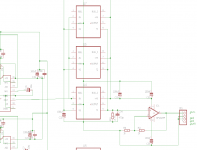
I was thinking of using Murata's 3 terminal (LCL) capacitors in the dac to 844 and also on all power supplies close to the chips.
eg:
DSS6NF31C223, (22nf) which is -20db at 2Mhz and -70 at 20Mhz for psu decoupling and possibly a DSS6NZ82A103 (1nf) -20db @ 6Mhz in the dac outputs.
Its not helpful of Murata not to state the inductance although it can be calculated I suppose.
This device probably has ceramics, and I read somewhere they cannot stand (do not like) audio frequencies across zero: the capacitance varies and smears the sound. That is why I said go for film.
But:
Having pondered on your 5 MHz interference: it looks like the clock signal on the 1541 is coupled (capacitatively: close running leads; inductively - intertwined leads; maybe an earthing problem around the chip - the two earthes should be connected as close and quick as possible imho) in one or another way to the output of the TDA1541. That then could be a layout problem.
I've scrapped the dac & await a simpler kit from Hong Kong so I will see how the 844 behaves with this one.This device probably has ceramics, and I read somewhere they cannot stand (do not like) audio frequencies across zero: the capacitance varies and smears the sound. That is why I said go for film.
But:Having pondered on your 5 MHz interference: it looks like the clock signal on the 1541 is coupled (capacitatively: close running leads; inductively - intertwined leads; maybe an earthing problem around the chip - the two earthes should be connected as close and quick as possible imho) in one or another way to the output of the TDA1541. That then could be a layout problem.
Also, I am thinking of using a IL715 110mbps 4 input digital isolator to connect the I2S signals in a Teac PD HO1 slot loading cd player, direct to the new dac, bypassing the spdif input and CS8412.
http://www.nve.com/Downloads/il71x.pdf
Ian
Either should work fine. Slightly better slew rate at + and - 15 VDC. I couldn't hear any difference when I tried it. 🙂Hi all
Any idea about the ideal supply voltage for AD844? Is +/-15v better than +/-12v?
There seems to be no difference betqeen 12v and 15v for me either. I just wanted to double check.
I also found that adding a small resistor in series at the output (after the buffer) makes the sound more solid and stable. I guess it reduces the sensitivity to interconnect cable.
I also found that adding a small resistor in series at the output (after the buffer) makes the sound more solid and stable. I guess it reduces the sensitivity to interconnect cable.
Hi all
Any idea about the ideal supply voltage for AD844? Is +/-15v better than +/-12v?
I have a Salas shunt running at 80 mA for both channels and at 9.5 volt (I have no more headroom). And then I have abundant decoupling at the sockets. But no zobel.
Could someone tell me if this is correct for the output of an AD1862?
Would I be missing some components here?
View attachment 586065
Thanks
Simon
I'd use separate bypass caps on each power pin of AD844 & OPA627 instead of one large cap. I used 0.1uf~0.22uf C0G/NP0 ceramics, and they are quite good.
I'd use separate bypass caps on each power pin of AD844 & OPA627 instead of one large cap. I used 0.1uf~0.22uf C0G/NP0 ceramics, and they are quite good.
Where do you source those caps? C0G caps are hard to find with such large value.
I just use multiple nichicon muse kz near to the chip. So far I am happy with the sound. C0G are very good but sometimes when I mix different types of caps in parallel the sound may become uneven. For example if i use PPS cap in parallel with black gate on the supply pins of TDA1541a it worse than black gate cap alone. On the othen hand pps caps are very good for decoupling the current divider pins of tda1541a
Where do you source those caps? C0G caps are hard to find with such large value.
Yes, they are hard to find and expensive. It happens that I had a chance to buy a reel of C0G at a very good price. The only place I'd not use ceramic is the power pin of AD1860. Yet, this is on my DAC. Ceramics may be still good on yours.
Yes I can do that the same as you can see on the +VS of the AD1862 100uf bypassed with 100n. Is there anything else. I noticed in previous diagrams there is a capacitor from pin 2 of ad844 to ground. Is that needed and what size should it be?I'd use separate bypass caps on each power pin of AD844 & OPA627 instead of one large cap. I used 0.1uf~0.22uf C0G/NP0 ceramics, and they are quite good.
Cheers
Simon
regarding http://www.diyaudio.com/forums/digital-source/227677-using-ad844-i-v-95.html#post4918956 like to ask
- does tz output go to + IN of op627
- how can we add dc offset null loop
- does tz output go to + IN of op627
- how can we add dc offset null loop
NP0/C0G are really excellent capacitors in so many respects yet I put them right at the bottom of the pile when choosing decouplers. For a couple of reasons :
1) Their Q is extremely high so they're more likely to resonate with other reactive elements in the circuit.
2) They're difficult to find and expensive above 100nF, and 100nF has a fairly large case size (1206) and hence relatively high parasitic inductance.
1) Their Q is extremely high so they're more likely to resonate with other reactive elements in the circuit.
2) They're difficult to find and expensive above 100nF, and 100nF has a fairly large case size (1206) and hence relatively high parasitic inductance.
Friends
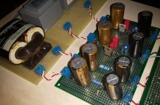
I built completely from scratch using matrix board cards (Eurocard double face) my new DAC with PCM1704 and IV AD844 with how
he was treated in this thread from the suggestions of George and Torchwood treasuring all the relevant post.
My DAC is NOS. I give the signal I2s in the format used since 1704 by means of JLsounds I2SoverUSB card configured for this purpose.
The signal goes direct to the two chip-dac.
For the supply of 1704 I used a shunt power supply based on the TL431.
the IV supply for + and - 15V with separate power supplies based on the LT3080 regulator.
Only for the galvanically isolated region of I2SoverUsb a supply with the TL431, the rest is fed from + 5V of the PC via USB.
I fetch the out of the IV from the internal buffer. I also tried out directly by TZ. In this situation the sound of this machine is the best I've ever heard.
Simply magic. Sound concrete, rich, holographic. Wonderful.
These days I wanted to try to put two parallel 844 again using the internal buffer of one only. The improvement was very significant and tangible.
It seems to me that they can not go back.
Strangely, however, 'it is occurring, only when I put in dip socket stack of 2 x AD844, and not always of continuous, a noise, pop, as if burning wood in the fire.
As soon as remove the stack and put it back one 844 . OK !perfect silence.
Can you help me understand
What happen? I like too stacking.
However, I have set up the I/V card to also try a OPA627 as an external buffer = 2 Gain
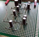
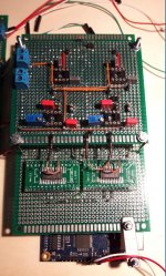
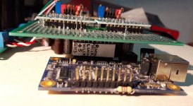


I just remember abraxalito who placed a small cap between pin 4 and 7.
Sounds like static. But just a hunch - load both pin 6 with 10k.
You have connected pin tz toegether i assume?
Sounds like static. But just a hunch - load both pin 6 with 10k.
You have connected pin tz toegether i assume?
Tank you triode
In the meantime, I solved the problem of Popcorn noise. To me it seemed triggered by an unstable contact of some pin 844 into the socket, perhaps for the tightening of the pin subjected to welding with the superimposed exemplary. I unsoldered all pins, cleaned up the pins and redid the welding by moving a bit higher up the mutual contact point. Repositioned the stack into the socket. Complete disappearance of the noise. It's working 24 hours and not more is resubmitted.
The suggestion by abraxalito of ceramic capacitor between the two supply rails I plan to put it into practice given the positive experience reported by some members.
TZ pins are welded like most 'sometimes suggested in this thread. In other words the pins 2,3,4,5 and 7 are welded
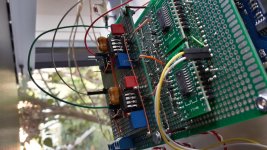

Last edited:
Tank you triode
In the meantime, I solved the problem of Popcorn noise. [-]
TZ pins are welded like most 'sometimes suggested in this thread. In other words the pins 2,3,4,5 and 7 are welded
View attachment 586419
Nice build by the way.
So you leave pins 1, 8 not connected to each other, like I do too.
What is the resistance (I see 470 pF micacapacitor), by the way, that you have on TZ? (=amplification of the I/V). I have 2k7 and 245 pF.
postscript. I tried a parallel resistance on the pin 2 input of 20 ohms, and with one chip it was -12 dB; with two -8 dB. I was just testing what the effect is. I will try 100 and 200 ohms just for fun; it does grab some input current and hence gets the input more in the class A limits , additional to 'massive' (double) paralleling . . .
Last edited:
Nice build by the way.
So you leave pins 1, 8 not connected to each other, like I do too.
What is the resistance (I see 470 pF micacapacitor), by the way, that you have on TZ? (=amplification of the I/V). I have 2k7 and 245 pF.
I think I will try parallel 844s on my new dual 1541 differential dac. (I'm using Iancanada's I2S to pcm board to produce the biphase simultaneous serial data)
A pair of 844 per channel with an OPA1632 differential opamp connected to their tz pins. This solves the 1541 output offset current issue and drives a transformer (but could be used single ended).
As the dac chip wants a very low load resistance, paralleled 844 should work even better. I plan on using 47r and 2n on the tzpins for paralleled 844.
thanksNice build by the way.
I use the same value on the TZ: 2k7So you leave pins 1, 8 not connected to each other, like I do too.
What is the resistance (I see 470 pF micacapacitor), by the way, that you have on TZ? (=amplification of the I/V). I have 2k7 and 245 pF.
My connection from 'Out of 1704 is directed to the pin 2 of 844
Pins 1 and 8 connected to the 20K trimmer only on the first 844
PS: I am going to use soon an OPA627 as an external buffer gain=2
Last edited:
NP0/C0G are really excellent capacitors in so many respects yet I put them right at the bottom of the pile when choosing decouplers. For a couple of reasons :
1) Their Q is extremely high so they're more likely to resonate with other reactive elements in the circuit.
2) They're difficult to find and expensive above 100nF, and 100nF has a fairly large case size (1206) and hence relatively high parasitic inductance.
abraxalito,
Thanks for the info. And, what would be your 1st choice for decoupler? I've tried several types of capacitor here. The C0G/NP0 is very close to bulky MKP's. As you've mentioned, film caps are with longer leads which may have more parasitic inductance. So, I put ceramics here.
- Home
- Source & Line
- Digital Line Level
- Using the AD844 as an I/V
