as I am building now I am all on to this 🙂 I can react a bit but not with as much insight as George -
Abraxalito gave some hints how to handle the power lines to the 844s.
I have:
a small (X5R footprint) Murata bead in the +/- supply, right after that a 10 uF in X5R and a 4.7 uF in in X7R ceramics too. Almost soldered on the pins.
I have, in case the chip oscillates, a plan to: solder a 10 uF on the case between pins 4 & 7. And add a snubber there too: 100 nF + 47 ohms.
Pin 5 in my view reflects anything it sees, sort of. So keep the outward inductance low. Right after the resistor and capacitor I have added a stopper resistor of 200 ohms, just like as if pin 5 were a grid of a valve or a gate of a fet.
So here my home brew. Jou can see the caps spraied around. Albert
as I am building now I am all on to this 🙂 I can react a bit but not with as much insight as George -
Abraxalito gave some hints how to handle the power lines to the 844s.
I have:
a small (X5R footprint) Murata bead in the +/- supply, right after that a 10 uF in X5R and a 4.7 uF in in X7R ceramics too. Almost soldered on the pins.
I have, in case the chip oscillates, a plan to: solder a 10 uF on the case between pins 4 & 7. And add a snubber there too: 100 nF + 47 ohms.
Pin 5 in my view reflects anything it sees, sort of. So keep the outward inductance low. Right after the resistor and capacitor I have added a stopper resistor of 200 ohms, just like as if pin 5 were a grid of a valve or a gate of a fet.
So here my home brew. Jou can see the caps spraied around. Albert
View attachment 580831
Thank you. I'll try those and the snubber is a good idea, maybe also a load on pin 6?
I may also try removing the .47uf dc blocking capacitor between pin 5 and the opa627 transformer driver. (I tried an op134 in case the 627 was part of the problem but made no difference).
I will also increase the capacitor to ground on pin 2: it was 10n, currently 1n.
With no capacitor, the oscillation amplitude drowns the audio, leaving noise and hum.
Ian
10 nF on pin 2 is way too much, pin 2 is input isn't it? The output impedance of the DAC chip will give a low cut-off, drowning dynamics.
The DC cap should not influence it. Try that stopper resistor. And specifically ensure the OPA is heavily decoupled from the AD. My AD844 has 10.000 uF, the BUF03 100.000 uF (wow). The PCM has a shunt (by Abbas, I'm lazy, and that sounds good).
See that the returnpath from the input to the next device exists. No loops in the eaurth, no potholes, or that will give garbage.
10n didn't sound dull. As the TDA1541 is current output (what is its output resistance?) and the input impedance of the 844 is 50r, 10n should not be too high surely?
Hi guys,
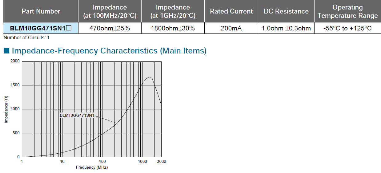
I just want to report that I've improved my I/V stage again. My current setup is based on OPA861, but I am sure it will work on AD844 also. As some of the experts here had mentioned that HF garbage from R2R DAC is unwanted and could upset the op amps easily, so I decided to do some experiment myself. I searched the catalog of Murata ferrite beads and found this special BLM18GG471SN1 is worth a try. To my surprise, the result is phenomenal. The smoothness is improved and more details is revealed. No side effect is found. As a ferrite bead could add 1 ohm DC resistance on signal path, but I think it's absolutely worth it. Here are the signals on my oscilloscope (GDS-1062A with 500Mhz probe). As for comparison, one channel is fitted with BLM18GG471SN1 and the other is from original circuit. The effect is pretty obvious.
Test signal: 100Hz sine 0dBfs
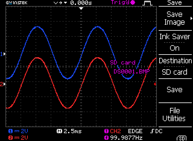
Result
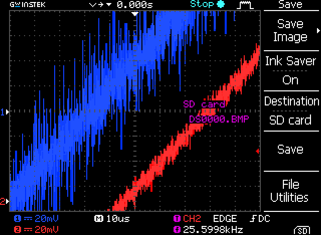
BLM18GG471SN1
Hi Canvas
I tried this tweak today on my tda1541a dac. The initial impression is positive. high and mid seem cleaner. sound stage seems clearer. but it's neither an a/b nor blind testing ;-)
Thank you and thanks to bkdog for giving me these ferrit beads.
cheers
Hi,
Excuze my bad understanding but where do you putt this ferrite beads exactly please ? (I'm opa861ed as well ! with TDA1541A). Between the curent output pin and the enter pin of the 861 ?
And Finally what do you loved after a 861 as I/V for the buffer ? (I have also here but in inverted position an opa 861 (P. Rogic's topology): very neutral but very sensitive to the power suplly rails, caps... quite happy... but if better solution, I 'd like to try! LM4562 as buffer ? BUF03 is said to be a little colored on the warm side ??)
Many thanks for these inputs !
Hi,
Excuze my bad understanding but where do you putt this ferrite beads exactly please ? (I'm opa861ed as well ! with TDA1541A). Between the curent output pin and the enter pin of the 861 ?
And Finally what do you loved after a 861 as I/V for the buffer ? (I have also here but in inverted position an opa 861 (P. Rogic's topology): very neutral but very sensitive to the power suplly rails, caps... quite happy... but if better solution, I 'd like to try! LM4562 as buffer ? BUF03 is said to be a little colored on the warm side ??)
Many thanks for these inputs !
The ferrite bead is connected to the tda1541a output pin at one end and to the ad844 at the other end.
I use a fet buffer from pin 5 of ad844 chip. The power supply makes a huge difference indeed. I use a discrete fet regulator with LM329 as voltage reference. at first I used a main discrete dual regulator shared with tda1541a and wm8804. then I try separate seg using lm317/337 with separate power transformer. it sounded much worse than the shared discrete reg. Then I made a second dual discrete fet regulators for the ad844 and the buffer. I am very hapy with the sound now.
Do you have a capacitor to ground on the dac output?
My 844 was oscillating at 5Mhz which was polluting the power supplies and the dac input looked even worse than yours without the bead.
I have abandoned the Raindrop_hui dac and purchased a single 1541 dac kit from Ebay so I can mod it with dem reclocking, I2S attenuators, Tentlabs or similar clock, better decoupling capacitors etc.
But I will rework my 844 I/v converter with the ferrite bead added, or even try a 3 terminal capacitor.
yes, I have 1n8 cap as in Pedja original design but it is placed after the ferrite bead. I use one ad844 per channel only. I tried the triple stacked ad844 and did not like it very much. it could be that the chips were not well matched as they were from different factories, I guess.
The screen shorts are not mine. They are Canvas's measurement. His chip is AD1860, if I remember correctly.
The screen shorts are not mine. They are Canvas's measurement. His chip is AD1860, if I remember correctly.
yes, I have 1n8 cap as in Pedja original design but it is placed after the ferrite bead. I use one ad844 per channel only. I tried the triple stacked ad844 and did not like it very much. it could be that the chips were not well matched as they were from different factories, I guess.
The screen shorts are not mine. They are Canvas's measurement. His chip is AD1860, if I remember correctly.
Thanks.
What value resistor and capacitor do you have on pin 5?
With parallel 1541a I used 100r & 10n, buffered by an OPA627 driving a transformer with a 5:1 step up. Then 50k Alps blue pot to Quad 405-2, driving Martin Logan Aeons.
Thanks.
What value resistor and capacitor do you have on pin 5?
With parallel 1541a I used 100r & 10n, buffered by an OPA627 driving a transformer with a 5:1 step up. Then 50k Alps blue pot to Quad 405-2, driving Martin Logan Aeons.
I have 1k5 takman rey resistor at pin 5 to ground in parallel with 1n cap. My buffer (K246 & J103) has no gain. I use Black Gate N 10uF as output cap.
works fine with the green wirewound from Rhopoint (516G) 1K and 1nf tin folded little styrene ! Would like to find the ideal bulk resistor though... (as Peter W. did with its tda1543) !
But yes, this is definitly the supply and its caps like the local decoupling which change the most the result... at least with my layout (AYA II 2014)...
But yes, this is definitly the supply and its caps like the local decoupling which change the most the result... at least with my layout (AYA II 2014)...
works fine with the green wirewound from Rhopoint (516G) 1K and 1nf tin folded little styrene ! Would like to find the ideal bulk resistor though[...]
I'm with a single AD1865 and active IV. To my ears I prefer the Rhopoints over the Z-foils 😉
Hi Canvas
I tried this tweak today on my tda1541a dac. The initial impression is positive. high and mid seem cleaner. sound stage seems clearer. but it's neither an a/b nor blind testing ;-)
Thank you and thanks to bkdog for giving me these ferrit beads.
cheers
hi quantran,
Glad you have some improvement over your DAC. Now, I inserted another ferrite bead into the current path (in series with the old one) and I got further improvement. I don't have the exact PN at hand, but it's also from Murata with large resistance on Mhz range. I guess everyone can try different value here. I'm fine with my current setup.
Poting
works fine with the green wirewound from Rhopoint (516G) 1K and 1nf tin folded little styrene ! Would like to find the ideal bulk resistor though... (as Peter W. did with its tda1543) !
But yes, this is definitly the supply and its caps like the local decoupling which change the most the result... at least with my layout (AYA II 2014)...
Yes, Rhopoint wirewound is pretty amazing here. It beats my S102K without sweat. The sound stage is 3D now!
hi quantran,
Now, I inserted another ferrite bead into the current path (in series with the old one) and I got further improvement. [--] I'm fine with my current setup.
Poting
Did you add a 1-2 nF (such as film!! not ceramic) in between the two? Should improve too.
And then - - it should also be possible to bridge this nascent filter to have a minimum at double the clock frequency. At least I once made it for a TDA1543 and it worked like a charm. That said, I should revisit this old idea.
My experience with ferrite beats is opposite. Yes on initial listening
the impression is darker like more quiet details are there but you
dont get something for nothing. Music somehow looses a certain
life. Sound stage more constrain. Listen longer & see if your findings
are similar to mine. Although I've not use beats as per discribe here,
the effects are similar to anywhere I place them especially in signal
or supply path
Cheers
Did you add a 1-2 nF (such as film!! not ceramic) in between the two? Should improve too.
And then - - it should also be possible to bridge this nascent filter to have a minimum at double the clock frequency. At least I once made it for a TDA1543 and it worked like a charm. That said, I should revisit this old idea.
No cap between them, but I not sure if the extra capacitance will affect the distortion. I will try that.
Did you add a 1-2 nF (such as film!! not ceramic) in between the two? Should improve too.
And then - - it should also be possible to bridge this nascent filter to have a minimum at double the clock frequency. At least I once made it for a TDA1543 and it worked like a charm. That said, I should revisit this old idea.
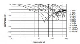
I was thinking of using Murata's 3 terminal (LCL) capacitors in the dac to 844 and also on all power supplies close to the chips.
eg:
DSS6NF31C223, (22nf) which is -20db at 2Mhz and -70 at 20Mhz for psu decoupling and possibly a DSS6NZ82A103 (1nf) -20db @ 6Mhz in the dac outputs.
Its not helpful of Murata not to state the inductance although it can be calculated I suppose.
Attachments
Rhopoints... Ferrites...
Hi Canvas, I'd have to agree if you can afford them go with the Econistor's. Expensive to get here in the states. Ferrite... I had some ferrite cores on hand. I wound one turn around a FT-37-43. Not much difference on the PCM1704 DAC which is well behaved. The TDA1541 DAC was a small improvement. 🙂Yes, Rhopoint wirewound is pretty amazing here. It beats my S102K without sweat. The sound stage is 3D now!
- Home
- Source & Line
- Digital Line Level
- Using the AD844 as an I/V