In contrast to the AD844 the OPA860s buffer input (pin5) is fully separated from the current conveyor output (pin8).
The TZ pin (pin5) of the AD844 is the common joint of the current conveyor output and the buffer input.
Ahhhhhh well that makes sense now. So 844 is not so one-off after all...
You know which one I would recommend 😉
The exact same IC in series, my guess.
I'm revising this thread to establish what the best option is for non-oversampling application (not necessarily just the 1541 either). I'll outline them so newcomers can pick. These current amps sound promising, in many devices with current dacs, early rompler synths and other fx. why didn't they use them in the first place!
(guess; budgeting )
I never got to try this, maybe one day.
Cheers George
This is almost what I am using right now, but I replaced the pot with servo for zero DC drifting. IMHO, 1 OPA861 is likely having 4~5 AD844 stacked. I even tried 4 stacked OPA861. The sound improved in the mid tone, but slightly degrades the higher and lower range. Finally, I settled with single OPA861.
I'm trying to understand what you guys are talking about here ... this means that one OPA860/1 could replace 4 stacked AD844 in a TDA1541A NOS configuration? a simple schematic for testing purposes would be very welcomed in this case 🙂
Hi,
Input impedance wise the OPA86x are similar to a quad-stack of AD844s (12.5R vs. 50R) but bias current wise I don't think, that the OPAs run on four times the AD's bias ... and You need to keep in mind the +-5V supply limit on the OPAs.
jauu
Calvin
Nope ... I said discrete Buffer ... it'd be of course the Calvin buffer or a slightly simpler non-cascoded version of it 😀The exact same IC in series, my guess.
Input impedance wise the OPA86x are similar to a quad-stack of AD844s (12.5R vs. 50R) but bias current wise I don't think, that the OPAs run on four times the AD's bias ... and You need to keep in mind the +-5V supply limit on the OPAs.
jauu
Calvin
I never got to try this, maybe one day.
Cheers George
As an N-pseudo transistor device, I might suggest the N-version of Jean Hiraga's Le Prepre for using the OPA860. It would imply having the input on the emitter, and that "should have" a low impedance - lower than Hiraga's transistors (with an Rbb of 2-3 ohms the 2SB737/2SA1775 already is capable of loading a PCM1704 anyway I think in such a configuration.)

my 2 ¢
Hi,
with a CFP Darlington in place of T1 and T11 You can achieve "Emitter"-input impedance values in the mOhm range using standard small signal transistors like the BC327/337.
For current sourcing DACs like the PCM179x series a PNP transistor results in a more efficient circuit (lower idle currents, lower heat power losses).
jauu
Calvin
In the thread I read some concern about the capability of the AD844 to sink current, such as +/- 1 mA from the 1704 or even worse, the +/- 2 mA of the 1541. However, I saw the following in the datasheet:
This implies that the 850 micro amperes idle current on pin 2 can significantly go out of the input idle current boundaries, and accomodate larger currents than its own idle current. The current 'limit' - lets call it the class-A - boundaries seem not to exist or be significant for the developers.
However, this is not to say getting the input resistance down by paralleling or with an additional resistor of say 100 ohms, is not effective, but this might have more to do with the loading of the PCM1704. Maybe I misunderstood the postings relative to this though - and the goal was indeed to get the input impedance right...
I know I am a late adopter so my remarks are way out of synch, apologies.
I will first try the add-a-resistor option, and add 200 ohm.
The AD844 performs very well in applications requiring current-to-voltage conversion. Figure 42 shows connections for use with the AD568 current output DAC. In this application, the bipolar offset is used so that the full-scale current is ±5.12 mA, which generates an output of ±5.12 V using the 1 kΩ application resistor on the AD568.
This implies that the 850 micro amperes idle current on pin 2 can significantly go out of the input idle current boundaries, and accomodate larger currents than its own idle current. The current 'limit' - lets call it the class-A - boundaries seem not to exist or be significant for the developers.
However, this is not to say getting the input resistance down by paralleling or with an additional resistor of say 100 ohms, is not effective, but this might have more to do with the loading of the PCM1704. Maybe I misunderstood the postings relative to this though - and the goal was indeed to get the input impedance right...
I know I am a late adopter so my remarks are way out of synch, apologies.
I will first try the add-a-resistor option, and add 200 ohm.
In the thread I read some concern about the capability of the AD844 to sink current, such as +/- 1 mA from the 1704 or even worse, the +/- 2 mA of the 1541. However, I saw the following in the datasheet:
This implies that the 850 micro amperes idle current on pin 2 can significantly go out of the input idle current boundaries, and accomodate larger currents than its own idle current. The current 'limit' - lets call it the class-A - boundaries seem not to exist or be significant for the developers.
However, this is not to say getting the input resistance down by paralleling or with an additional resistor of say 100 ohms, is not effective, but this might have more to do with the loading of the PCM1704. Maybe I misunderstood the postings relative to this though - and the goal was indeed to get the input impedance right...
I know I am a late adopter so my remarks are way out of synch, apologies.
I will first try the add-a-resistor option, and add 200 ohm.
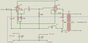
My IV converter works very well using the AD844 and OPA627 as shown below.
There are paralleled TDA1541As which are now working with none of the noise initially experienced once the dem oscillator was connected as shown.
see thread http://www.diyaudio.com/forums/digital-source/163971-parallel-tda1541a-dac-noise-new-post.html
As you can see 100r is used on pin 5, which gives a no signal volts of ~.4v (hence the need for the 0.1uf cap on the input to the OPA627 to avoid DC through the transformer.
Ian
Attachments
How much dc is coming from the TDA1541's?
Cheers George
With my paralleled dacs, as each 1541 has a 2ma offset, with no signal there is 0.4v across the 100r resistor on pin 5.
You could get rid of the of the .1uF coupling cap if you use the dc offset nulling pins 1 & 8 on the AD844.
Also you should try it without the output transformer and take the output straight from pin 6 of the OPA627, as transformer coupling will colour the sound somewhat.
Cheers George
Also you should try it without the output transformer and take the output straight from pin 6 of the OPA627, as transformer coupling will colour the sound somewhat.
Cheers George
You could get rid of the of the .1uF coupling cap if you use the dc offset nulling pins 1 & 8 on the AD844.
Also you should try it without the output transformer and take the output straight from pin 6 of the OPA627, as transformer coupling will colour the sound somewhat.
Cheers George
I didn't think the offset nulling would work with that size of offset.
The transformer is an effective low pass filter but I intend to try without it connected, however it has a 1:5 ratio so I will need to change the gain of the OPA627.
Thanks, Ian
I didn't think the offset nulling would work with that size of offset.
The transformer is an effective low pass filter but I intend to try without it connected, however it has a 1:5 ratio so I will need to change the gain of the OPA627.
Thanks, Ian
Yes the nulling pins will work, but look back through these pages for a post I did regarding this, as what's on the data sheet for the value of the nulling pot (20ohms) is a typo, and I gave the correct value somewhere, and I can't remember now what that was.
You also have dc offset nulling pins 1 & 5 on the OPA627 you can use. Maybe use a little on both the AD844 and OPA627
As for the transformer being a LP filter yes, but you have one already on the TZ of pin 5 on the AD844, as you have it now with 100ohms and 10000pf it's -3db at 160khz, bring this down to -3db at 80khz by either making the cap 20000pF or raising the resistor to 200ohms.
And adjust the total gain using the feedback resistor of the OPA627.
Cheers George
Last edited:
Yes the nulling pins will work, but look back through these pages for a post I did regarding this, as what's on the data sheet for the value of the nulling pot (20ohms) is a typo, and I gave the correct value somewhere, and I can't remember now what that was.
You also have dc offset nulling pins 1 & 5 on the OPA627 you can use. Maybe use a little on both the AD844 and OPA627
As for the transformer being a LP filter yes, but you have one already on the TZ of pin 5 on the AD844, as you have it now with 100ohms and 10000pf it's -3db at 160khz, bring this down to -3db at 80khz by either making the cap 20000pF or raising the resistor to 200ohms.
And adjust the total gain using the feedback resistor of the OPA627.
Cheers George
I will try listening without the transformer in circuit but I noticed that very high end dacs eg some of Audio Note's nos dacs use a transformer between dac & valve output stage, with no other filtering.
(I do have an base model AD1865 based Dac1 and it did sound better when I substituted the valve output stage for my transformers, but it runs a close second to my 1541 dac, especially with the 844/627 I/v stage & transformer).
I am confused by your lp filter recommendations though. I thought that for nos dacs, theory dictated a steep filter with -3db at 20kHz to minimise any interaction (sum & difference frequencies?) between audio harmonics and the 44k sampling frequency. So why do you not advocate setting the -3db point much closer to 20K - eg 40K?
Having said that, the only time I am really aware of any artifacts is with solo male bass or baritone. Maybe its because the psychoacoustic 'masking' phenomenon doesn't mask it with solo voices? Female vocal soloists are rarely affected.
wouldn't it be great if we can do away with any low pass circuit
or even a dc blocking cap. these things are evil in the analog path
or even a dc blocking cap. these things are evil in the analog path
You mean: no capacitor on pin 5 at all? Sounds like a good idea.
I hear real NOS thinking there.
I hear real NOS thinking there.
Big problem with the 844 i/v, its oscillating at 5Mhz which is polluting the supplies. I've tried to cure it but no luck so I removed it and connected the transformer directly to the dacs in parallel across 50r.
No rf, no noise from the paralleled dac outputs but yet the sound is lacking body compared to the oscillating 844.
Then another disaster - the 5v supply shorted out so gave up for now and switched the Raindrop Hui dac pcb for my Audio Note AD1865 Dac1 pcb driving the transformer directly (with 220R on the dac current output).
Big problem with the 844 i/v, its oscillating at 5Mhz which is polluting the supplies. .
You have something wrong then as it's quiet as a church mouse. Or your seeing a transfer of the dac noise via it's input and then getting amplified.
Cheers George
You have something wrong then as it's quiet as a church mouse. Or your seeing a transfer of the dac noise via it's input and then getting amplified.
Cheers George
When I have fixed the blown 5v supply, and assuming it hasn't blown all the 5v chips, I will investigate further. The dac output is as clean as expected with the i/v resistor and transformer.
The oscillation was a sinewave of +-80mv. Maybe it was the stripboard layout - not ideal for very wide band opamps.
- Home
- Source & Line
- Digital Line Level
- Using the AD844 as an I/V