In that regard the OPA861 -utilizing the same basic topology- is more flexible,
Calvin
Hi again, just to double check, is the 'trans-impedance pin' on 844 same as 'external IQ pins' on other chips?
Thanks
Hi,
in short: No!
Pin TZ (5) of the AD844 equals Pin C (8) of the OPA860 and the OPA861, its buffer-less brother.
Pin 5 of the OPA860 is the Input to its buffer ... in that it equals the AD844.
The Iqadjust Pin of the OPAs is Pin 1
Compared to the simplified circuit diagramm of the AD844 (p13#20) its an additional input that would define the value of the ib named current sources and hence it'd set the idle current of the whole Transconductance stage.
The Q implies that the circuit function is not fully understood.
So let's go back to the AD844's datasheet, p13#20 again.
As the lower half of the circuit is the exact complement of the upper half, its sufficient to analyze just one of the halves.
The emitter of a NPN is connected to Pin2.
The idle current flowing through the NPN towards +Vs is mirrored by the four PNPs, a (full) Wilson Current Mirror, into Pin TZ(5).
The idle current is defined by the Vbe of the NPN.
Now the NPN's base is connected to the base of a second NPN whose emitter is then connected to Pin3.
Let's assume now that Pin3 will be connected to 0V/gnd.
As the NPN at Pin3 is connected as a Diode (collector-base-joint), the current source Ib forces a current through it that results in a corresponding Vbe.
At the same it forms a simple current mirror with the first NPN, connected to Pin2.
The same applies to the complementary half.
If all transistors and the complementary-half ones are matched, then it is logical that the idle currents through the Pin2-connected transistors and their associated current mirrors must match also and that Pin2 settles at the same value as Pin3.
As the emitters are low-impedance nodes, Pin2 forms a virtual 0V/virtual gnd.
So, the value of Ib defines the idle current of the whole circuit.
It is fixed with the AD844, but variable from the outside via Pin1 with the OPA86x.
This and the fact that the buffer stage of the OPA860 is fully independent from the transconductance stage make it a more versatile stage than the AD844 (that on the other hand features offset nulling via Pins 1and 8).
jauu
Calvin
yikes! blown away by the detail there, but the line of info up is great 🙂Hi,
in short: No!
Pin TZ (5) of the AD844 equals Pin C (8) of the OPA860 and the OPA861, its buffer-less brother.
Pin 5 of the OPA860 is the Input to its buffer ... in that it equals the AD844.
I'm still curious about the current mirror though Calvin... will it 'squash' or 'clip' the signal? if over driven...
Thanks
Last edited:
Hi,
there are at least two mechanisms that can drive the circuit into clipping.
The first and rather unlikely is a too high output voltage.
Since the output voltage is the product of signal current amplitude times the load impedance (at TZ-Pin), very large load impedances could create output voltages coming very close to the supply lines (voltage clipping).
The OPA86xs are more prone to this due to their lower powers upply line limits.
The second and more probable case here is that the the peak signal currrent exceeds the idle current (current clipping).
That´s one of the reasons to parallel the AD844 (a second is to reduce the input impedance at Pin2).
Paralleling rises the idle current, resp. divides the signal current, so that the requirement of Iidle > Ipeak_signal is met.
With an overall idle current value of 6.5mA of the AD844 it´s quite unlikely that the idle current in the branches of the transconductance-stage alone exceed 1mA as that could lead to considerable amounts of heat power loss, especially if the AD844 is supplied from >>5V supplies.
Unfortunately the idle values are not split up into the transconductance´s and the buffer stage´s part.
It´slikely that the buffer consumes at least 2-3mA itself.
The 1mA idle current would be needed as a minimum for a TDA1541 with a typical full scale output current of 4mA (+-2mA).
The OPA861´s quiescent current (and OPA860´s transconductance stage alone) can be variied between 4.3-7.0mA ... with the buffer stage the OPA860 can vary between 9.5mA and 13.5mA, indicating that the buffer runs on 5.2-6.5mA.
The OPAs can idle at higher values because their supply lines are restricted to +-6.5Vmax.
Judging by the DS-information I´d assume that a single OPA86x could replace at least two AD844 (of course running on +-5V supplies instead .. which suffices for up to +-3.9Vpp --> 2.75Vrms of signal output voltage).
A single OPA86x set to highest idle current should suffice for a TDA1541.
As said before ... since the output parameters of the DAC-Chip are clear defined and limited it´s easy to see, that once the transconductance-stage´s parameters exceed the requirements, there will (and can!) be no clipping.
jauu
Calvin
But I really mean overloading the mirrors as an artificial effect, will it clip, or will it 'saturate gradually' is what I'm asking >.>
allyBut I really mean overloading the mirrors as an artificial effect, will it clip, or will it 'saturate gradually' is what I'm asking >.>
If you mean the 844, from what I heard with the 1.2mA output of the pcm1704, with a "single" 844 there is no hard clipping, but a compression dynamically to the sound, I suppose you can call that 'saturate gradually' or "soft clipping".
Cheers George
Hi,
one could measure the distortion characteristic over output amplitude.
Either THD rises slowly (´gradually´) or pops up at a certain level (hard clipping).
jauu
Calvin
ps. I still don´t get it why You insist on that clipping theme, when a properly designed stage will never run into clipping with this application. 🙄
Hi,
one could measure the distortion characteristic over output amplitude.
Either THD rises slowly (´gradually´) or pops up at a certain level (hard clipping).
jauu
Calvin
ps. I still don´t get it why You insist on that clipping theme, when a properly designed stage will never run into clipping with this application. 🙄
WRT clipping, that is correct.
WRT AD844 vs OPA860, IMV there are other factors to consider.
The 844 runs much high voltage rails which allows the transistors to run more in a linear capacitance vs voltage region. This is very important in an open loop current conveyor circuit.
The 860 has advantage of higher quiescent current for the OTA = lower distortion but it's all squashed into max +-6.5V rails.
Choose your poison - but it's clear to me either solution is inferior to a really
well designed discrete solution.
But - they are very nice elegant solutions avoiding complexity of discrete.
T
Hi,
talking about complexity 😀
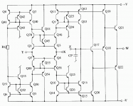
Seeing the elaborated current mirrors I at least wouldn´t want to build those in discrete fashion (pic shows a more detailed circuit of the AD844).
You need to be as hardcore as a Paradise Phonoista to put up with the transistor matching requirements. 😛
On the other hand of course the low current limits of the integrated circuit imho seriously limit the range of applications.
Paralleling whole circuits seems a rather ´plumb´ workaround.
But then from my numerous smulation runs, it seems that the CMs don´t need to be so elaborated.
They don´t improve numbers as much as expected, but are much more sensitive to matching and more prone to oscillation.
Supply voltages and level of bias currents play a more important role THD-wise.
And sonically it more than once seems that simpler can be better. 😉
For DACs with current offset (sinking or sourcing types, like the TI PCM179x series) a discrete single-ended current conveyor (see Jocko-Homo for example) seems more elegant.
Such one You have to build discrete anyway, as there are no ICs with SE-internals.
jauu
Calvin
talking about complexity 😀
Seeing the elaborated current mirrors I at least wouldn´t want to build those in discrete fashion (pic shows a more detailed circuit of the AD844).
You need to be as hardcore as a Paradise Phonoista to put up with the transistor matching requirements. 😛
On the other hand of course the low current limits of the integrated circuit imho seriously limit the range of applications.
Paralleling whole circuits seems a rather ´plumb´ workaround.
But then from my numerous smulation runs, it seems that the CMs don´t need to be so elaborated.
They don´t improve numbers as much as expected, but are much more sensitive to matching and more prone to oscillation.
Supply voltages and level of bias currents play a more important role THD-wise.
And sonically it more than once seems that simpler can be better. 😉
For DACs with current offset (sinking or sourcing types, like the TI PCM179x series) a discrete single-ended current conveyor (see Jocko-Homo for example) seems more elegant.
Such one You have to build discrete anyway, as there are no ICs with SE-internals.
jauu
Calvin
Attachments
Hey Calvin, WOW!! where did you get that from??? You must know someone.
I've asked Barrie Gilbert designer for it from AD for it, but he said it was lost in his archives somewhere.
Cheers George
I've asked Barrie Gilbert designer for it from AD for it, but he said it was lost in his archives somewhere.
Cheers George
Last edited:
Hi,
I found it on my computer ... don´t know how or when it got there 🙄
Based on the above schematic I simmed the circuit.
According the DS the overall idle current of the AD844 is 6.5mA.
The current consumption of the simulated circuit gave that value when the input transistors and current mirrors idled at 820µA (RQ=33k).
That´s lower than the +-1mA peak-peak signal current a TDA1541 produces in the upper, resp. the lower half of the circuit (we had expected that already, didn´t we?).
The THD-sim resulted in a 3rd harmonics dominated spectrum (0.0249%).
Doubling the current by halving RQ (as a equivalent for paralleling devices) reduced the THD to 0.0081% and changed the spectrum to 2nd harmonic dominated.
Reducing the CM´s idle current to 200µA (I think I remember to have seen that value claimed somewhere in this thread before, RQ=135k) raised the THD to 0.226% and the spectrum shows the uneven harmonics (up to the 9th) higher than H2.
Btw. simmed with 1mA idle current Zin was 15R, with 200µA it gave~50R, the value stated in the DS.
The harmonics distribution due to the transistors running into class-B/cutting off could explain the sonic differences between single and paralleled AD844s.
jauu
Calvin
Attachments

Hi,
talking about complexity 😀
Seeing the elaborated current mirrors I at least wouldn´t want to build those in discrete fashion (pic shows a more detailed circuit of the AD844).
You need to be as hardcore as a Paradise Phonoista to put up with the transistor matching requirements. 😛
On the other hand of course the low current limits of the integrated circuit imho seriously limit the range of applications.
Paralleling whole circuits seems a rather ´plumb´ workaround.
But then from my numerous smulation runs, it seems that the CMs don´t need to be so elaborated.
They don´t improve numbers as much as expected, but are much more sensitive to matching and more prone to oscillation.
Supply voltages and level of bias currents play a more important role THD-wise.
And sonically it more than once seems that simpler can be better. 😉
For DACs with current offset (sinking or sourcing types, like the TI PCM179x series) a discrete single-ended current conveyor (see Jocko-Homo for example) seems more elegant.
Such one You have to build discrete anyway, as there are no ICs with SE-internals.
jauu
Calvin
Yes - as you guys slowly pull apart these devices it is being revealed - that
they are essentially devices that are designed to run closed loop and are
optimized as such.
Example, current mirrors are not degenerated, all BJT's are run at a fraction
of the current that you really want etc.
A really good discrete current conveyor, be it designed as a simple cascode,
with mirrors or folded cascodes, can run real world distortion of around
0.002% or even much less and hold it at high frequencies.
The circuit can be fairly simple but importantly they sound great when done
right.
T
George, guys,
thank you for a thread about I/V from current out dacs and particularly pcm1704
It Is very Interesting using AD844 stacked or not here
If that can be of help I saw a thread that Patrick (AKA EUVL) running http://www.diyaudio.com/forums/head...rtable-headphone-amplifier-2.html#post4799516 about headamp where he used AD844 output followed by BUF634 / LH033 / discrete equivalent
you are comparing AD844 to discrete DDNF but did you compared to SEN I/V
Last edited:
with a "single" 844 there is no hard clipping, but a compression dynamically to the sound, I suppose you can call that 'saturate gradually' or "soft clipping".
Either THD rises slowly (´gradually´) or pops up at a certain level (hard clipping).
jauu
Calvin
ps. I still don´t get it why You insist on that clipping them
Let me clarify.
Current mirrors, available through these pins are quite significant because they behave much like 'valves' with respect to the distortion they produce. This makes these ICs, part of them comparable to valves, but in solid state form. Now in music production, soft clipping a signal, even to extremes is a sought after effect.
The reason I think these ICs are significant, over op-amps, is (I think) op-amps don't allow as much flexibility and therefore induce Hard Clipping, which not as nice an effect.
What I'm saying/asking is, current mirrors are kind of like solid state take on valves. Significant because they obviously more robust than valves.
If what you say about saturation is true, there's potential in areas other than I/V conversion 😉
Does this makes sense... current mirrors = robust valves, artistic effect.
One can use a valve as I/V, which is popular with lampizator projects, but current mirrors can be a direct, more robust replacement, I think if they do behave so much like valves in terms of how they behave at extremes.
you are comparing AD844 to discrete DDNF but did you compared to SEN I/V
No, all I wanted was simple to implement with no major surgery to my cdp a readily available $4 chip (the 844), that gave in the end very good results with a readily available OPA627 buffer. Others may have.
Cheers George
thank you for reply George
that cheap solution Is what I am looking also for a quick and reliable upgrade when space Is tight
would you please give more details about your final Implementation of output buffer for pcm1704
regards
that cheap solution Is what I am looking also for a quick and reliable upgrade when space Is tight
would you please give more details about your final Implementation of output buffer for pcm1704
regards
George, guys,
thank you for a thread about I/V from current out dacs and particularly pcm1704
It Is very Interesting using AD844 stacked or not here
If that can be of help I saw a thread that Patrick (AKA EUVL) running http://www.diyaudio.com/forums/head...rtable-headphone-amplifier-2.html#post4799516 about headamp where he used AD844 output followed by BUF634 / LH033 / discrete equivalent
you are comparing AD844 to discrete DDNF but did you compared to SEN I/V
Hi samoloko, I was the guy playing with Pedja's DDNF stage. No. I read about the SEN however never tried it. I recommend a voltage buffer on the output of the DDNF just as we would with an AD844. These days I am more or less DDNF. My triple stack is still in a chassis however doesn't get much play.
thank you for reply Torchwood421,
I know that you have reviewed both
appreciate very much your contribution
I have tried SEN with PCM63 and found It better than D1, moded D1 (with current sources)
as I said I really like to find a simple solution using best of both worlds ICs and discrete
I know that you have reviewed both
appreciate very much your contribution
I have tried SEN with PCM63 and found It better than D1, moded D1 (with current sources)
as I said I really like to find a simple solution using best of both worlds ICs and discrete
Discrete
Hi samoloko, Just my opinion however I'd go for a discrete solution. Either Pedja's Discrete DDNF circuit with a OPA627 buffer stage, or abraxilito's discrete CFB I/V stage. You can find that one on abraxilito's page. As I still have a number of DDNF boards I have yet to try his CFB stage however it looks superb on paper. A good JFET based stage such as the SEN could be very good although not a low impedance device. It reminded me a bit of a JFET version of one of the Lampizator guy's circuits. Although I haven't looked at his page in a long time. 😉
thank you for reply Torchwood421,
I know that you have reviewed both
appreciate very much your contribution
I have tried SEN with PCM63 and found It better than D1, moded D1 (with current sources)
as I said I really like to find a simple solution using best of both worlds ICs and discrete
Hi samoloko, Just my opinion however I'd go for a discrete solution. Either Pedja's Discrete DDNF circuit with a OPA627 buffer stage, or abraxilito's discrete CFB I/V stage. You can find that one on abraxilito's page. As I still have a number of DDNF boards I have yet to try his CFB stage however it looks superb on paper. A good JFET based stage such as the SEN could be very good although not a low impedance device. It reminded me a bit of a JFET version of one of the Lampizator guy's circuits. Although I haven't looked at his page in a long time. 😉
- Home
- Source & Line
- Digital Line Level
- Using the AD844 as an I/V