Thks again George yes I do have the heat sink.
Btw where did you get the pcb for the Buf ?
I made mine P to P, advantage is I have the
regs on the same board as well more compact
Cheers
Btw where did you get the pcb for the Buf ?
I made mine P to P, advantage is I have the
regs on the same board as well more compact
Cheers
I used the 1amp regs on the cdp, the board I got on ebay ages ago, some one was selling them for $10 or so.
Cheers George
Cheers George
Hi George
Got the Buf working so it isn't fake lol.
Btw must you used such a big value cap on
the Buf 03. Im testing it out with just 100uf
but in order for the buffer to work I have to
use a dc blocking cap at the output. Without
this cap I can't null dc. Though I have no
scope, some how I suspect the low value
cap is creating oscillation. Any ideas ?
Many thanks again
Which dac?
I know you shot this at George.... If your using a TDA1541(A) you need the 2 mA null circuit. Adjust that for zero give or take a few mV's at the input of the AD844(s). If your buffering the output off pin 5 TZ... You should have only a few mV's there. If you have a null circuit on your BUF03.... It should have enough range to counter those few mV's. It sounds like you have no offset null to counter the rather large TDA1541's offset.Hi George
Got the Buf working so it isn't fake lol.
Btw must you used such a big value cap on
the Buf 03. Im testing it out with just 100uf
but in order for the buffer to work I have to
use a dc blocking cap at the output. Without
this cap I can't null dc. Though I have no
scope, some how I suspect the low value
cap is creating oscillation. Any ideas ?
Many thanks again
Hi torchwood
Thks for the advice. Well the buffer is actually use for
neither . Lol. My concern is more on why do I need a
DC blocking cap to be able to get the Buf 03 working .
Thks
Thks for the advice. Well the buffer is actually use for
neither . Lol. My concern is more on why do I need a
DC blocking cap to be able to get the Buf 03 working .
Thks
You don't need to have a dc coupling cap for the BUF03 itself as it's dc offset can be nulled out with it's own nulling trimpot pins.
You need to start with minimal dc offset from the dac output, then null the AD844's with their own nulling, pins and finally the BUF03 as in the first sentence.
The whole lot from dac ouput to buf03 output can be dc coupled if you start at the begining.
Cheers George
You need to start with minimal dc offset from the dac output, then null the AD844's with their own nulling, pins and finally the BUF03 as in the first sentence.
The whole lot from dac ouput to buf03 output can be dc coupled if you start at the begining.
Cheers George
Advice
Hard to give advice with so little to go on. It suggest that whatever your buffering has an offset. I'd put the blocking cap in front of the BUF03 on the input. The null circuit on the BUF03 should then zero. I am usually able to get better then 0.1 mV's. BUF03's as George mentioned are like a freight train drive wise and have a rich sound. I rather enjoy them. 😀Hi torchwood
Thks for the advice. Well the buffer is actually use for
neither . Lol. My concern is more on why do I need a
DC blocking cap to be able to get the Buf 03 working .
Thks
Thanks George & Torchwood.
I actually tested the Buf directly from Cdp
out which itself has only 3mv of DC.
Still head scratching as to why I cannot
null the DC output of Buf without placing
A DC blocking cap. Will make some power
supply changes & test it tonite again.
Many thanks again guys
I actually tested the Buf directly from Cdp
out which itself has only 3mv of DC.
Still head scratching as to why I cannot
null the DC output of Buf without placing
A DC blocking cap. Will make some power
supply changes & test it tonite again.
Many thanks again guys
Still head scratching as to why I cannot
null the DC output of Buf without placing
A DC blocking cap.
Do you mean the 5kohm trimpot on the Buf03 hasn't got the range you need to zero the offset?
Attachments
Hi George
It does have the range but strangely it only works
if I hang a cap at the output . I suspect there's oscillation
from the regs. Will make some changes & let's see what
happens. Im using a tracking reg config with LT 317/337
to lower noise . Design is from Acoustica.org.uk.
Re reading LT data sheet & perhaps reason might be
due to no install of 1N4002 at the output of reg.
Anyway will try & see what happens
Many thanks again
Hi George
It does have the range but strangely it only works
if I hang a cap at the output . I suspect there's oscillation
from the regs. Will make some changes & let's see what
happens. Im using a tracking reg config with LT 317/337
to lower noise . Design is from Acoustica.org.uk.
Re reading LT data sheet & perhaps reason might be
due to no install of 1N4002 at the output of reg.
Anyway will try & see what happens
Many thanks again
You really need an oscilloscope for this kind of work. Be careful. You could burn your speaker easily.
Hi George, Torchwood
Need a little advice. I can't seem to null the dc offset.
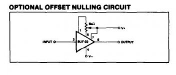
According to the schematics that I have, the trim pot is 5K
pin 1 of trim pot is connected to pin 1 of Buf , wiper of trim pot is
connected to pin 7 of Buf & pin 3 of trim pot is connected
to pin 5 of Buf. Is this correct ? Or have I mistaken it & that wiper
should be connected to Ground ?
Many Thanks
Need a little advice. I can't seem to null the dc offset.
According to the schematics that I have, the trim pot is 5K
pin 1 of trim pot is connected to pin 1 of Buf , wiper of trim pot is
connected to pin 7 of Buf & pin 3 of trim pot is connected
to pin 5 of Buf. Is this correct ? Or have I mistaken it & that wiper
should be connected to Ground ?
Many Thanks
Sorry guys just to confirm does the input have to be shorted
when adjusting DC Offset ?
Thanks again
when adjusting DC Offset ?
Thanks again
Hi George, Torchwood
Need a little advice. I can't seem to null the dc offset.
According to the schematics that I have, the trim pot is 5K
pin 1 of trim pot is connected to pin 1 of Buf , wiper of trim pot is
connected to pin 7 of Buf & pin 3 of trim pot is connected
to pin 5 of Buf. Is this correct ? Or have I mistaken it & that wiper
should be connected to Ground ?
Many Thanks
Pins 1 5 and 7 on the Buf03 is correct, wiper to 7
Sorry guys just to confirm does the input have to be shorted
when adjusting DC Offset ?
Thanks again
Shorted or connected to the TZ of the AD844, not open circuit.
Cheers George
Back to work...
Hi Jaffrie, I am back to work now after my knee replacement. I see George answered your question. On work days I am unable to check the thread however PM me if you need a quick answer. I will see it much sooner. Hope your making good progress. 🙂Many thanks again George
Knee replacement !!!!!
Yes its working thks a million torchwood.
It does have a very clear sound with no grain.
Presentation is a little forward in my set up
though.
Yes its working thks a million torchwood.
It does have a very clear sound with no grain.
Presentation is a little forward in my set up
though.
Shouldn't be forward, the BUF03 has a big sound, with plenty of deep bass drive.
If you have a coupling cap anywhere, it may not be big enough causing the bass to roll off a little and giving that forward sound?
Cheers George
If you have a coupling cap anywhere, it may not be big enough causing the bass to roll off a little and giving that forward sound?
Cheers George
- Home
- Source & Line
- Digital Line Level
- Using the AD844 as an I/V