The latest issue of Linear Audio (https://linearaudio.net/volumes/2269) has a fabulous article by our very own Scott Wurcer & Sam Groner that shows COG ceramic caps have less distortion than polystyrenes... It dispels the myth that "all ceramic caps are bad" (COG and NPO are excellent) - is well worth a read!
On the topic of bypass caps, I'd like to know why the default value is 100nF. How do we determine the ideal value for a particular circuit or the bigger the better?
And, what would be your 1st choice for decoupler?
I've not been following along very closely here, are we talking about decoupling for the AD844? If so then I'd use several 10uF/1206 X7R between the pins as 100nF isn't nearly enough to be using for decoupling a classAB output stage (such as found in AD844).
On the topic of bypass caps, I'd like to know why the default value is 100nF.
Its a good question I can only take a (relatively experienced) guess at answering it. The default value has been 100nF for as long as I've been building circuits with opamps in them (a few decades) - over which time capacitor technology has developed immensely. 100nF suggested in opamp DSs used to be a film type of cap and often there was a recommendation to add 10uF or so electrolytic in parallel.
100nF is really an RF decoupler, its probably there to assist maintaining stability at the opamp's unity gain (1-10MHz typically for a lot of cooking-grade opamps). Its not contributing anything in the audio band as its reactance at 20kHz is about 80ohm.
I would suggest a starting point for knowing how big a cap to choose is to determine the peak output current pulled from the supply. For a classA circuit not so much capacitance is called for because the current is going to be relatively constant compared to classAB.How do we determine the ideal value for a particular circuit or the bigger the better?
This is off topic. I found 0.1uf~0.22uf to be the best for op amps decoupling. Higher value will reveal more mid-bass but it will lose really deep bass. That's said you lose a bit 30~100Hz, but gain 100~200Hz. Same as 0.1uf~0.22uf paralleled with large caps. Well, this is what I've experienced so far.
If someone can affect yesterday I finally tried using the external buffer with the OPA627 with gain = 2. Already the stack with two 844 had produced an important increase in quality 'listening. I have no words to describe well what they listen now. In one word: Amazing 😀😀. It seems to have reached the perfect reproduction.
I use the Lightspeed as a passive attenuator. An amp MyRef Fremen Edition and speakers Diapason Adamantes II.
I can only express my gratitude to those who started this thread, and to all those who have spoken and taught me everything.
Thanks George, but also to all those who have developed this thread.
My Christmas Gift

Schematic for AD844 + Buffer(gain stage)
After trawling through this thread for too long I have come up with a schematic diagram which may help others. This shows how to use the AD844 triple stack with buffer (2 x) as suggested by the OP Georgehifi. hopefully link this to the opening post.
Cheers
Simon
After trawling through this thread for too long I have come up with a schematic diagram which may help others. This shows how to use the AD844 triple stack with buffer (2 x) as suggested by the OP Georgehifi. hopefully link this to the opening post.
Cheers
Simon
Attachments
Just realized, that the AD1862 also put out around 1mA, and you used 2 x stacked AD844's. You should up this to 3 stack, as there was a marked improvement again with 3 of them with the PCM1704, as it will lower the input impedance as see by the 1864 to around 10ohms which is better for a current output dac and gives it more current headroom as well.
Cheers George
Cheers George
George if "you" refers to me because I use the double stack of 844 want to clarify that I run it with 1704 .... anyway if you refer me feel very recommendable upgrading to triple stack .... an improvement it seems incredible .... but I am ready to rearm the welderJust realized, that the AD1862 also put out around 1mA, and you used 2 x stacked AD844's. You should up this to 3 stack, as there was a marked improvement again with 3 of them with the PCM1704, as it will lower the input impedance as see by the 1864 to around 10ohms which is better for a current output dac and gives it more current headroom as well.
Cheers George
George if "you" refers to me because I use the double stack of 844 want to clarify that I run it with 1704 ....
Sorry no I mean Niss_man he uses the AD1862.
Cheers George
ok ..... it seemed that niss_man adopts the triple stack in the schematic in attachment ... but you believe the triple stack a serious improvement for 1704?Sorry no I mean Niss_man he uses the AD1862.
Cheers George
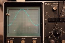
Some results: PCM1704 @ 44kHz, 24 bits depth, IAN PCM with JTAIL; NOS (no digital filter); double AD844, BUF03: it is 1,95 V RMS (on my B&K).
A perfect signal without pre or post echo
The staircase, I have a small cap 150 pF mica between PCM104 and AD844, and 245 pF mica on pin 5/TZ, with 2k7 (3k//10k); output is 1,95 V RMS (B&K)
Of course I can decrease the TZ frequency roll-off, but it is OK like this, I have no super tweeter, can't hear above 13 KHz anyway &I have a tube amplifier where driver and output both roll off at 50 KHz..

Comment - The steps on the staircase seem not equal, slanting, this is due to my old Philips scope, on which the DC/DC takes a long time to settle.
So that looks great!
On the scope no difference with a TDA1541 of course. 🙄
An externally hosted image should be here but it was not working when we last tested it.
A perfect signal without pre or post echo
The staircase, I have a small cap 150 pF mica between PCM104 and AD844, and 245 pF mica on pin 5/TZ, with 2k7 (3k//10k); output is 1,95 V RMS (B&K)
Of course I can decrease the TZ frequency roll-off, but it is OK like this, I have no super tweeter, can't hear above 13 KHz anyway &I have a tube amplifier where driver and output both roll off at 50 KHz..

Comment - The steps on the staircase seem not equal, slanting, this is due to my old Philips scope, on which the DC/DC takes a long time to settle.
So that looks great!
On the scope no difference with a TDA1541 of course. 🙄
What sort of noise (level and frequency) are you getting at 2mV per div with a scope shot from the buf03 output?
Cheers George
Cheers George
What sort of noise (level and frequency) are you getting at 2mV per div with a scope shot from the buf03 output?
Cheers George
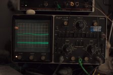
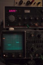
With iTunes turned off, the USB connected, the output of BUF03 is flat, is a bit thick. When I connect my B&K, it measures 0,09 mV in the audio band.Same for pin 2 TZ.
The scope is a thick line (using a 1:1 probe) and there is a little 100 Hz jump but this varies in time, maybe an artefact from the dangling wires.. I have 100 ohms out, cabon composite.
(Pin 6 is 0,15 mV again maybe a ground loop issue of the measurement).

The thick line does not trigger the locking even when the timebase is turned to min timeframe of 0,2 uS, well just a slight tick, that I also have seen on my shunt of one side of the PCM1704.
So not bad at all.
Last edited:
George, I see that I have more noise on scope than your typical 200 microV build.
Is that correct? Or is this just the HF noise like I infer?
Albert
Is that correct? Or is this just the HF noise like I infer?
Albert
George, I see that I have more noise on scope than your typical 200 microV build.
Is that correct? Or is this just the HF noise like I infer?
Albert
Yours is good, especially if you have no filter cap across the TZ resistor?
http://www.diyaudio.com/forums/digital-line-level/227677-using-ad844-i-v-8.html#post3338183
Cheers George
Are you getting the funny spiral on the 20khz sine wave (above link)?? as I never did get around to see if it was my smp bench light doing it?
Cheers George
Cheers George
Yes. I will use triple stack. My circuit isn't together yet, just parts at this stage. But thought diagram would help others.Sorry no I mean Niss_man he uses the AD1862.
Cheers George
- Home
- Source & Line
- Digital Line Level
- Using the AD844 as an I/V

