^ What they said plus check the series resistor values on the board. For twisted pair they should be circa 70-90ohm (plus source resistance of the driver) to match the Ethernet's 100ohm impedance.
The better way is to use proper differential signaling techique - whether it's use of bare LVDS or transformer coupled (as used in Ethernet).
The better way is to use proper differential signaling techique - whether it's use of bare LVDS or transformer coupled (as used in Ethernet).
Last edited:
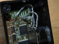
It took me 15 mins to rewire them, as it's all solid core, need a tweezers to hold the wire, as the RJ45 socket is PCB type, quite hard to avoid short of wires.
Have you seen your pcb & clock are broken?
Attachments
^ What they said plus check the series resistor values on the board. For twisted pair they should be circa 70-90ohm (plus source resistance of the driver) to match the Ethernet's 100ohm impedance.
The better way is to use proper differential signaling techique - whether it's use of bare LVDS or transformer coupled (as used in Ethernet).
Hi,
How do you turn the data, Bclk and Frame sync SE signal into differential signal?
Thanks
That looks like left overs from the glue gun only.
Sorry confused me.
I2S Grounding Questions
Please comment:
1. If I use a 3.3V to 5V I2S buffer, I don't physically attach those the ground wires to the signal wires do I? If not, where would the ground wires run?
2. On my DAC board there's only BCK, DATA, and FS. The nearest grounding point on the DAC board is 5 inches away.
Thanks
Please comment:
1. If I use a 3.3V to 5V I2S buffer, I don't physically attach those the ground wires to the signal wires do I? If not, where would the ground wires run?
2. On my DAC board there's only BCK, DATA, and FS. The nearest grounding point on the DAC board is 5 inches away.
Thanks
Please comment:
1. If I use a 3.3V to 5V I2S buffer, I don't physically attach those the ground wires to the signal wires do I? If not, where would the ground wires run?
2. On my DAC board there's only BCK, DATA, and FS. The nearest grounding point on the DAC board is 5 inches away.
Thanks
I don't understand what you're suggesting in your 1st question.
For your 2nd question, if you must use that DAC, then the best alternative is to scrape some soldermask off and expose some of the copper from the ground plane.
I also face similar issue with my dac, I will need to drill a small hole and scrape off the soldermask at the bottom layer of the PCB where the ground plane is.
I use the TDA1541A chip in my DAC. It uses 5V logic.
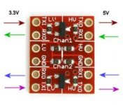
To use the Amanero board, I need a 3.3V to 5V level shifter like this:
So...I just run the I2S sigal grounds to the power ground on the level shifter?
Also, shouldn't the signal wires be the same length as the ground wires?...
To use the Amanero board, I need a 3.3V to 5V level shifter like this:
So...I just run the I2S sigal grounds to the power ground on the level shifter?
Also, shouldn't the signal wires be the same length as the ground wires?...
Attachments
Hi,
How do you turn the data, Bclk and Frame sync SE signal into differential signal?
Thanks
Use the RS-485 or LVDS transmitter/receiver ICs...
For level shifting you could use TTL-compatible CMOS ICs such as HCT series.
Throw-in a reclocker near the DAC which will reclock data, BCLK, LRCLK lines with MCLK clock. Make the MCLK connection the best you can.
But TDA1541 doesn't require 5V level logic signaling - it's kinda weird as per HtP/ecdesign threads. Use these attenuators recalculated for 3v signaling and be happy, or use the 3v directly.
Use the RS-485 or LVDS transmitter/receiver ICs...
Is the ADN4665/4666 is right kind?
I use the TDA1541A chip in my DAC. It uses 5V logic.
To use the Amanero board, I need a 3.3V to 5V level shifter like this:
So...I just run the I2S sigal grounds to the power ground on the level shifter?
Also, shouldn't the signal wires be the same length as the ground wires?...
I think a better solution is to use a digital isolator as the IL 175. Thus also break ground loops. You just have to connect VD1 to 3.3V (Amanero side) and VD2 to 5V (TDA1541 side)
All wires must be the same length.
Regards
ADN4667/ADN4668 seem to give much better layout, 1.5ps RMS jitter contribution by ADN4667/ADN4668 combo thru HDMI cable.Is the ADN4665/4666 is right kind?
HDMI cables work nicely for I2S transmission.
Is the ADN4665/4666 is right kind?
Do you know this module? Teleporter Digital Transfer Module
Regards
ADN4667/ADN4668 seem to give much better layout, 1.5ps RMS jitter contribution by ADN4667/ADN4668 combo thru HDMI cable.
HDMI cables work nicely for I2S transmission.
Agree, will try to get a set of these chip to try out.
Thanks
Didn't notice, worth a look and can save some work.
Thanks
ADN4667/ADN4668 seem to give much better layout, 1.5ps RMS jitter contribution by ADN4667/ADN4668 combo thru HDMI cable.
HDMI cables work nicely for I2S transmission.
According to the spec twisted pairs cable can be used as a transmission medium.
I think a better solution is to use a digital isolator as the IL 175. Thus also break ground loops. You just have to connect VD1 to 3.3V (Amanero side) and VD2 to 5V (TDA1541 side)
All wires must be the same length.
Regards
yes they should ideally, if its all being reclocked a bit of difference wont cause a big problem. I didnt mention it on the previous page as it seemed like I already had my work cut out getting a ground for each signal =) plus it sounded like there was a long cable afterwards, so 20mm probably wasnt a big deal in the greater scheme of things. ribbon cable is a good way to assure the same length though so I just suggested that.
more general stuff for the thread
when twisted pear suggest twisted pair can be used, they mean actual twisted pair cable, not home twisted silver wire, but 100ohms ethernet cabling, I favor Belden Cu in PTFE network cable, but yes HDMI is a better cable construction IMO.
I tell you what though, nothing beats not needing to drive a long cable to your dac in the first place.... just use an isolator and reclock locally at the dac if you can. people really shouldnt be treating this like a separate peripheral, its part of the dac, it should be as close to the dac as possible, you should not use one of these HDMI or teleporter things just to enable you to install it somewhere you have enough room for your shunt regs... the thing is tiny, you should have room for it in any dac, putting it in another case just so you can use a low noise power supply is walking *** backwards
Last edited:
- Home
- Vendor's Bazaar
- USB to I2S 384Khz - DSD Converter