I got two 15ohm/2W resitors from my local Fry's ($.99). The voltage dropped down to about +/-15.5V. OPA627 still get hot (but acceptable). However, the 15ohm resistors get HOT now 😀
Salas, regarding the sound of various opamps, the best solution is to try some free samples 🙂 I just ordered two LM4562 free samples from National. These dual opamps seem to be very neutral.
Marin
Salas, regarding the sound of various opamps, the best solution is to try some free samples 🙂 I just ordered two LM4562 free samples from National. These dual opamps seem to be very neutral.
Marin
Its normal they get hot. I hope that the nationals will fair better because 627 isn't my cup of tea. Did you take care of the coupling caps?
"C13, C14 BlackG NX Hi-Q 47uf/6.3V coupling cap
C15, C16 remove coupling cap
C109, C110 remove coupling cap"
C15 and C16 are easy to confirm as bypassing C13 and C14 but the thread is a bit ambiguous regrading C109 and C110. Are C13 & 14 the only coupling caps ahead of the RCA jack? My DAC1 was apart yesterday to repair a snapped ground lead on the RCA jacks (pure junk, AudioNote silvers soon on order) and I took the opportunity to swap a pair of spare Blackgate 100uF N-types for the 22uf Elna C13 and 14 in my early model. It wasn't subtle and made me realize a very large part of the excess top-end 'texture' I've been chasing in my amps was the DAC1. The swap wasn't 100% positive so far but it'll be a while before the BGs come up to full charge at such low offset voltages.
Are C109 and C110 also coupling caps? I'm ordering new RCA jacks, may as well do a few more upgrades on the next teardown. One will be replacing the 100 uF N-types with pairs of 22uf NX Hi-Q connected in the recomended 'inductive cancellation' mode bypassed with a 0.1 NX Hi-Q. It may be pure bunkum but I'll survive the $12 risk. 😉 Thx in advance.
15 and C16 are easy to confirm as bypassing C13 and C14 but the thread is a bit ambiguous regrading C109 and C110. Are C13 & 14 the only coupling caps ahead of the RCA jack? ... Are C109 and C110 also coupling caps?
In the latest version of DAC1, C13 and C14 are 1000uf/6.3V. Each is bypassed by a film cap and by a ceramic cap. This is easy to confirm with a multimeter (and by looking at the circuit traces when you remove the caps). I swapped them today with 47uf black gates 🙂 If you want to use L-cancelation, you can add another 47uf.
I was reluctant to put only 47uf (instead of 1000uf), but it seems that in earlier versions, DAC1 used 22uf bypassed by ONLY ONE ceramic cap. See this thread.
Marin
Thanks marinsimina. 1000uf is an unusual choice, my early version DAC1 measures 99kohm to ground on the next-stage side of the cap. I'ld be interested in hearing your impressions of the cap change.
Any idea if C109 and C110 are also directly in the signal path?
Any idea if C109 and C110 are also directly in the signal path?
rdf said:Any idea if C109 and C110 are also directly in the signal path?
Yes, C109 and C110 are on the signal path and you will have to remove them. C109 (SMD film cap) is in parallel with C13 and with C17 (100nf ceramic), while C110 is in parallel with C14 and C16. You can check with a milivoltmeter that the voltage (~0.1-0.2V) across C109 is the same as the voltage across C13 (or C17). The 47uf NX hi-Q sound fine and I expect an improvement after a few days of break-in 🙂
I just noticed that I made an error in my earlier post. I wrote:
In fact, the 330pf caps are: C34, C35, C36, C37 (you can confirm this from one of the pictures posted by Bas). But it makes sense to change C27, C28, C29, C30 as well (with 680pf Wima FKP2, according to AD1853 data sheet).C27, C28, C29, C30 WIMA FKP2 330pf feedback loop (see AD1853)
Marin
Well, now I'm totally confused. Swapping out C13, 14, 15 and 16 for a pair of Blackgate N 100uF had a relentless, almost unlistenable result. It wasn't any better two days later. Tonite I pulled the cover again to check for the existence of C109 and C110 (nope, early versions) and, seeing as Benchmark went to the trouble of bypassing the original 22 uF caps, added a pair of 0.1 Nx Hi-Q to the 100s. It made a major improvement. The balance is still tipped towards the mids (via headphones as well) but it's no longer the jackhammer from before.
Now I've been swapping caps for decades, since my Hafler DH-101 daze, and I've never heard the magnitude of change resulting from these two swaps. I've also used Benchmark product professionally for nearly as long and know these boys are flinty-eyed, dyed in the wool engineers and the furthest thing from tweaks. They don't bypass caps on religion. So my question is, what's happening in the circuit around C13 and C14 that made them add ceramic bypasses to electrolytic caps in prod run 1, and then add a further film on run 2? They unquestionably did it on prosaic engineering reasoning, anyone have a clue as to what it could be?
Incidentally, even with the 0.1 bypass it's still not there. I might install a staggered set of values using the entire NX Hi-Q range. The caps are dirt cheap in these small values and I'll learn something, end up with a major improvement in sound or with luck both.
rdf, I did not experience any sound degradation by using only 47uf NX Hi-Q. In fact, I got an improvement, but I do not know how much was from the blackgates or from replacing the rectifier bridges and the regulators. I do not have an explanation for your situation, but one idea might be to try 47uf 🙂 And I do not believe it is anything special aout the (repeater) opamps that follow the caps.
Anyway, using ceramic and electrolytic caps (other than black gate NX) on the signal path is not recommended. audioengr also talks about these issues here.
Marin
Anyway, using ceramic and electrolytic caps (other than black gate NX) on the signal path is not recommended. audioengr also talks about these issues here.
Marin
Maybe the 47uF NX Hi-Q has significantly less high frequency impedance than the 100uF N? I was shocked at what I heard, enough so that test gear was coming out to see if something broke. I ordered the full range of NX Hi-Q today and we'll see what happens!
rdf said:...Swapping out C13, 14, 15 and 16 for a pair of Blackgate N 100uF had a relentless, almost unlistenable result. It wasn't any better two days later...
Just for the record (and I'm sure you'll find plenty of other references to the like...) I went to my mates house and had a listen to his Leak Valve Amp. Half way through my time there, felt like I had a headache coming on.
I questioned as to whether something had been changed in his system, to which he replied that he had swapped-in some Black Gate caps... I remember well, by the time I arrived home I felt like I had
a migrane !!
As a general rule - I don't suffer from Migrane's (!!!)
The BG's are known for requiring a rather lengthy burn-in time.
Just my observation, anyway.
Best to all, -Andy-🙂
RDF: I think they increased to 1000uf in run 2 so to cut the corner frequency many times. In such a way cap distortion goes much down even by keeping the cheap Al. lytic component grade.. Being big they probably bypassed further to help its inevitably worse hf imp vs the original 22uF. Since you measure 99k on its next stage input why not checking out a say 2uF plastic like Auricap and the like for educational purposes?
Thx salas. I wasn't aware of that aspect of Alu electrolytic behaviour. Makes sense. I considered Auricaps (about the only film I like) but couldn't see how to sensibly fit a pair in the case. Some of the MultiCap look as if they'll fit as well. My spare 0.22 uF caps Auricaps, good for a corner frequency just over 7 Hz, may go in temporarily as you say for educational purposes.
My DAC 1 is about 14 months old and I want to at least bypass some of the extra buffer Opamps.
I don't use volume pot, balanced out or headphone.
I have some 47uF/6.3v BG NX caps to swap as well.
Just did an upgrade to an Oppo DVD with good results with them.
After that I have some AD8620 samples I want to try also but that will be the second wave.
Does anyone have a decent schematic or block diagram of this thing ??
I actually asked Benchmark for this about 9 months ago but they would not provide it...
Thanks
Todd
RDF:
About that phenomenon W. Jung wrote in Audio in 1980. Maybe you have experienced better sound when using a 1000uF cathode bypass instead of a 100uF in tube circuits? Especially when the DC rating of the cap is near the cathode bias voltage. Late (& great) Nobu Shishido advised low voltage, bigger than needed caps there too.
With a drop of hot-glue on the phones sockets back boxes you can rest the Auricaps on there, and their flying leads should be long enough to solder where the original caps leads were. Let us know if you listen to the Auricaps there.
7Hz is ok, but if they sound good, a final 1-2uF value is going to eliminate even the slight phase turn around 20Hz. Just to be nitpickers.
Todd: Haven't seen a detailed schematic, never.
salas said:RDF:
Todd: Haven't seen a detailed schematic, never.
Hopefully someone on this forum will have at least a reverse engineered schematic or even a block diagram...
Otherwise I'm going to go blind reverse engineering another surface mount design !!
As I mentioned I asked Benchmark for this but they would not budge (even though I offered to sign a Non-Disclosure agreement).
They were however more than interested in what mods I would make.
If Benchmark were really smart, they would offer a version without all the "features" that was just a basic DAC !!!
Todd
Hi salas. I must have been aware of that once, I bought those articles on the newstand. 🙂 I long ago gave up on large caps in the cathode circuit for fixed or LED bias. Re: Nobu Shishido, large caps have other advantages in a cathode circuit beyond inherent low distortion such as keeping local degeneration at an absolute minimum into low frequencies. I see many cathode-biased amplifier output circuits posted with caps too small to maintain a good damping factor at the very bottom end for example. If you look at Broskie's circuits they use massive cathode bypass caps as well.
That's indeed what struck me as so strange about the BG/DAC1 change, no tube circuit ever responded as strongly to a cap flip. In fact these caps are used pulls from cathode circuits. That, and hard-engineering Benchmark's aggressive bypassing, can't help but have me believe the circuit somehow requires a low HF coupling impedance. A range of quality caps values gives me the luxury of playing around at leisure. The first go will likely be all NX Hi-Q 47uF//22uF//0.47uF//0.1uF to create a broad plateau of HF null while maintaining the same cap type and construction.
That's indeed what struck me as so strange about the BG/DAC1 change, no tube circuit ever responded as strongly to a cap flip. In fact these caps are used pulls from cathode circuits. That, and hard-engineering Benchmark's aggressive bypassing, can't help but have me believe the circuit somehow requires a low HF coupling impedance. A range of quality caps values gives me the luxury of playing around at leisure. The first go will likely be all NX Hi-Q 47uF//22uF//0.47uF//0.1uF to create a broad plateau of HF null while maintaining the same cap type and construction.
I see that you go for a package cap tweak deal. All this will be very educating. See what's best. An assortment of BG, a 1000uF BG, or an Auricap. Anxious to know your findings. Gotta nail this wee DAC.
I'll let you know as things progress. Right now the 0.22uF Auricaps are in place and they may be the silver bullet for anyone who finds the V1 DAC1 cold and sterile.
Auricaps
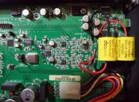
I changed the coupling caps to Auricap 2uF/200V. They are about the biggest fitting above the headphone jack ( I used hot glue, and attached them on it). I don't recommend a lower value in the V2 DAC1 with the 1000uF stock couplers because I saw less impedance in the following stage than the 99K that RDF saw in his V1 (with 22uF stock couplers). Auricaps have long flying leads that make it practical to replace the stock caps and find a place to attach them too. I believe that the certain space and position led other tweakers automatically to Blackgates. I don't know if BGs are the best for that because the Auricaps unlocked the DAC1 with so much balance and sweetness that I doubt any special lytic can match.
There is so much resolution and balance in this Benchmark that the stock couplers are a proven bottleneck as it turned out.
After the Auricap tweak, music unclogged. Slam, sweetness, resolution, highs, imaging, and everything really, unleashed but stayed locked and lost edge and grain. Sibilance is natural now.
I don't find DAC1 needing anything more after that. Since it retained its balance and did not transform. It merely unlocked.
For those seeking to change the DAC by changing op-amps and the like, I recommend very careful one by one steps. Because as I listen to it, its perfectly balanced for a broad musical spectrum. The wholesale upgrade that the Auricaps bring is much noticeable over headphones too. My Grados sound like ones again. Slam and sweetness is back. Much needed after 2 long nights of live music on a mixing desk 20m from a splitting loud stage.
I give some pics about the simple tweak.
Attachments
- Status
- Not open for further replies.
- Home
- Source & Line
- Digital Line Level
- Upgrading the Benchmark DAC 1?