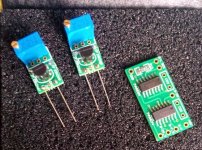
Welcome Bas,Look what the mailman brought!! Thanks Enrico.
Glad to know that you receive your parts

oh.... i thought i am the only one with oscillation problems and strange dc voltage measurements on the buffer board 🙂 ... happy that you guys are looking for a solution to fix it. otherwise very nice buffer but no use :-(
I am quite surprised about the oscillation problem that more then one of you face with the buffer 😕
I build and test one of the buffer board as per GB and another board with the identical circuit but I never have any kind of problems.
I know that Ross is trying to understand what can be the cause of the oscillation and this is a good news.
In the mean time is possible to see some picture of the board with oscillation to have an idea about the connections or the other component used?
Thanks,
Enrico
Here's mine. As you can see the voltage regulator/power supply for the buffer is in the left hand case, so something like 20cm of wire between supply and buffer. I was going to try setting the supply to 15v and using additional regulators right at the buffer, but maybe there's an easier solution?I am quite surprised about the oscillation problem that more then one of you face with the buffer 😕
I build and test one of the buffer board as per GB and another board with the identical circuit but I never have any kind of problems.
I know that Ross is trying to understand what can be the cause of the oscillation and this is a good news.
In the mean time is possible to see some picture of the board with oscillation to have an idea about the connections or the other component used?
Thanks,
Enrico

James,
I see that you don't use the board that I design and I can't understand from your picture which component you have installed in the buffer. If you think that can be a problem from the power supply too far you can try to put temporary the 2 DIYINK near the circuit using short connection even if I don't think that is a problem of power supply.
Sorry I can't help you, I hope Ross can give you some better support.
Regards,
Enrico
Apologies to confuse, that's an older picture which showed the distance from supply to buffer clearly. Here's one with the new buffer in place.James,
I see that you don't use the board that I design and I can't understand from your picture which component you have installed in the buffer. If you think that can be a problem from the power supply too far you can try to put temporary the 2 DIYINK near the circuit using short connection even if I don't think that is a problem of power supply.
Sorry I can't help you, I hope Ross can give you some better support.
Regards,
Enrico

I swapped to the new buffer board in an effort to stop this strange issue, but it's still the same.
I haven't tried using a real close supply again, but previously I had the power supply mounted much closer and didn't see the problem anywhere near as much.
You have any closer picture of the buffer board? Also I can't see how you set the DIYINK, 12V or 15V? You try to jump the connector between the 2 chassis, directly from the PSU to the buffer circuit and maybe with a biggest and twisted cable?
Not on my phone, I'll see if I can get one later.You have any closer picture of the buffer board? Also I can't see how you set the DIYINK, 12V or 15V? You try to jump the connector between the 2 chassis, directly from the PSU to the buffer circuit and maybe with a biggest and twisted cable?
The DIYINHK is set to +-12v
I'll try a few options when I get some spare time. Things are too busy here at the moment to do much.
Welcome Bas,
Glad to know that you receive your parts
Hi Enrico my CCS boards arrived as well, thanks very much.
James
i tried the diyinkh psu and the similar one form the "ant-x". the ant-x seems to be much better, even though it is almost the same design.I am quite surprised about the oscillation problem that more then one of you face with the buffer 😕
I build and test one of the buffer board as per GB and another board with the identical circuit but I never have any kind of problems.
I know that Ross is trying to understand what can be the cause of the oscillation and this is a good news.
In the mean time is possible to see some picture of the board with oscillation to have an idea about the connections or the other component used?
Thanks,
Enrico
the oscillation with the antx is less. the cable lengths from the psu to the buffer is important as well . it sounds much better when using a very short cable (2 cm).
i measure a at the buffer output more than 100mv compared to the dac output. in my case it is 3.1v and 3.15v ! i measure a voltage drope of 200mv over the buffer's input resistors which is a sign for oscillation. i assume that the oscillations can be very high frequency which is than difficult to measure with a normal scope. this behaviour is noticeable even supply the buffer with +-12v battery.
Hi All,
Is the 5V reg upgrade on the red main board necessary to undertake the 1/2 clock delay mod?
Cheers,
Nic
Is the 5V reg upgrade on the red main board necessary to undertake the 1/2 clock delay mod?
Cheers,
Nic
Hi Ross7. Connect the Buffer board as follows:
- Power supply to +12V, -12V, and GND. This power supply ground should be connected to the 8V analog power supply ground.
- Connect Right Main Board Pos to R+IN, Right Main Board neg to R-IN and Left Main Board Pos to L+IN, Left Main Board neg to L-IN.
- Do NOT connect anything to the OUT terminals at this time!
7. Physically mount the Buffer board to the Main Board or DAC board. See pictures at http://www.diyaudio.com/forums/digit...ml#post4230292
8. Power up the DAC and Buffer Board assembly.
9. TEST: Meter in Volts mode:
- Verify +12 and -12V on buffer board relative to DAC board ground.
- Measure from GND to R53 on far left which should be about -2.8V. This verifies the constant voltage circuit.
- The 4 IN points should be around 2.7V, and most importantly, within 0.01V of each other for each differential pair.
- The 4 buffer OUT points should measure about 0.1V higher than the IN points at around 2.8V.
10. Buffer Pot adjustment: (If only single ended capacitor output is to be used, then skip this step.) Put meter in MV measurement mode and put leads across R+ and R- Buffer OUT. Adjust pot to get close to 0.0mv. Do the same for L+ and L- OUT. Wait at least 30 minutes for the DAC to heat up and repeat adjustment. Turn off power.
11. Connect Cinemag, other output transformer, or differential capacitor leads to R+ and R- Buffer OUT and L+ and L- OUT. Turn on Power and check voltage across OUT leads. If ok then start listening to music.
I'm putting my buffer board into my DAC , your link on point 7 I have never got to work for me, are you able to re post the link to the pictures?
The main thing I am looking for is how the audio out of the main board connects to the buffer board, ie the ground and the hot wires, which one goes to which terminal.
Thanks
Buffer Mount Pictures
Sovereign1
Here is link to pictures of how I mounted the buffer board to the DAC board.
http://www.diyaudio.com/forums/digi...e-board-pcm1794-nos-dddac-38.html#post4230292
I built and installed the diyinhk PS but was unable to get it to oscillate.
I also built the Kubota PS but I cannot connect the grounds without blowing something. Will keep trying. I will report on results shortly
I tried them. But thought they gave an edgyness. So I preferred the ones the dac came with. Because I wanted to solder them out anyways. I got myself a quad of Shinkoh's (130R). I'm convinced I won't be able to hear the difference between the Shinkoh and the mills that they came with in a listening test. Both very natural. I got the idea that some background detail was better audible with the shinkoh. So they will remain in.I tried 135 (2X270) ohm Susumu RG's with success.
I've also soldered in the CCS's and could not really hear a difference. (Maybe there is something wrong with my hearing 😉)
Haven't had the courage to do the delay of the i2s yet.
Haven't had the courage to do the delay of the i2s yet.
The CCS makes an easily audible difference so that's very surprising.......
Sent from my iPad using Tapatalk
Sent from my iPad using Tapatalk
Maybe I was expecting a huge difference. Another problem is that I have fairly recently finished my 801A preamplifier. It would be much easier I think if I had lived with the same system for a long while. As it is my system is always in flux.The CCS makes an easily audible difference so that's very surprising.......
- Home
- Source & Line
- Digital Line Level
- Upgraded Single Board PCM1794 NOS DDDAC