Hi bas
I might have the clock board spare, I have two boards and I presume I only need one ?
James
I might have the clock board spare, I have two boards and I presume I only need one ?
James
Thanks James. I'll go with Enrico's offer. To save myself some postage and effort.I might have the clock board spare, I have two boards and I presume I only need one ?
James
Thanks Enrico,
Do you still offer the parts and soldering as an option?
If yes...I'd like to ask for the completest option.
1 CSS (if possible with part) and 1 Logic board (if possible with parts)
Last edited:
Well, I have the 1/2 clock delay with parts already soldered, the CCS boards but not the smd jfet for which you should ask to carlsors . For the CCS circuits in my DAC I use the 2SK246Y, I am very happy with and I have some spare.
Are you sure that you need just 1 CCS? For one dac board you need two of them...
Regards,
Enrico
PS: almost forget to mention that I am located in korea
Are you sure that you need just 1 CCS? For one dac board you need two of them...
Regards,
Enrico
PS: almost forget to mention that I am located in korea
Ofcourse. I need 2Are you sure that you need just 1 CCS? For one dac board you need two of them...
 .
.O yes please. If you are happy with them and have some spare.2SK246Y, I am very happy with and I have some spare
Awesome. I'd love to buy that from you.ell, I have the 1/2 clock delay with parts already soldered
I know..says so on your profile 🙂almost forget to mention that I am located in korea
Just fired up my buffer board! Sounding great! Exactly as advertised. A fuller, more textured sound much like the effect of four boards! Love it and I'm sure it will get better as it runs in!
I wonder how you, Ross, fixed JFETs to test them. I have got about 100 JFETs with the idea to test them for IDSS but they are so tiny so I have no idea how to fix them in place to test. What are resistor values for CCS Board , btw?
Can someone please advise the total resistance used to set the current in CCS?
If you go in the first page at the post #2 carlsor is explaining in detail the values needed for both the Jfets that can be used in the CCS circuit.
Regards,
Enrico
total resistance used to set the current in CCS
zz1969
It appears that you purchased 100 2SK208 JFETs so post #2 isn't going to help you much.
You will have to test each JFET to determine what source resistance will give you 0.40ma at 2.4V. You can always install 470 ohms in the fixed resistor position plus a 1K bourns trimmer pot which should work for over 90% of your JFETS if they are the "O" type. Adjust the pot until you measure 0.188V across the 2 TP points.
If you bought 100 JFETs with the idea of finding matched pairs or ones that would work with one or two SMD available resistor values without a pot - you have created quite a task for yourself.
I bought and tested 325 of these using a 6-pin SOIC fixture that I bought on ebay for about $35. I set up a breadboard and PS to provide the 2.4V and a way to measure the 0.40ma. A pot is put in the source position and adjusted until 0.40ma is obtained. Measure and record the pot resistance.
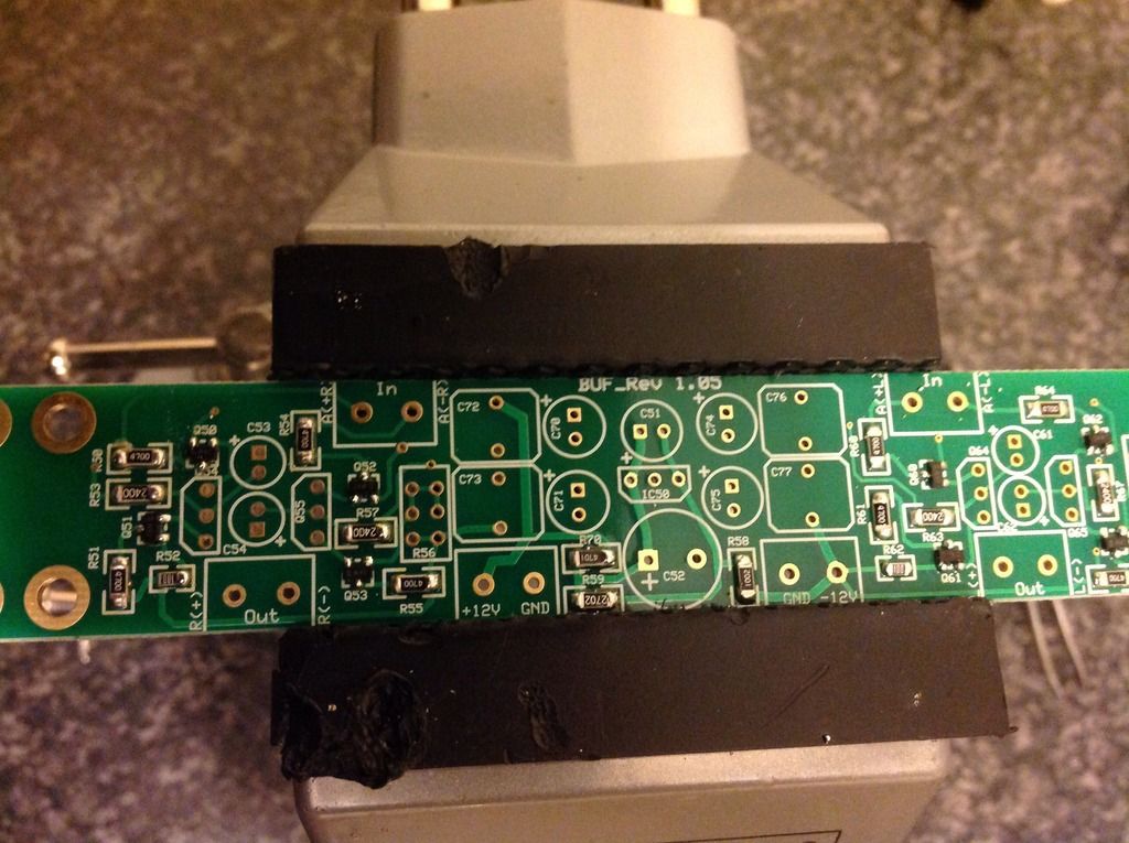
My buffer board coming together, big thanks to James for the pointer towards solder paste, I would be buggered without it!

zz1969
If you bought 100 JFETs with the idea of finding matched pairs or ones that would work with one or two SMD available resistor values without a pot - you have created quite a task for yourself.
I bought and tested 325 of these using a 6-pin SOIC fixture that I bought on ebay for about $35. I set up a breadboard and PS to provide the 2.4V and a way to measure the 0.40ma. A pot is put in the source position and adjusted until 0.40ma is obtained. Measure and record the pot resistance.
Hey, Ross! Yes, that was the idea. But now I see it's quite a task 🙂 I'll use a pot. Thanks.
Pardon for breaking with the current topic but does anyone have any thoughts on leaving the inductors and resistors in the voltage path if your running seperate bellesons on each
channel for digital and analog. Also running a seperate 5 Volt and 8 Volt Power Supply.
Seperate 8 Volt for each analog channel and the 5 Volts to main board to run Shift Register and the digital. Running the USB of another 5 Volt.
Thanks,
jgwtriode
channel for digital and analog. Also running a seperate 5 Volt and 8 Volt Power Supply.
Seperate 8 Volt for each analog channel and the 5 Volts to main board to run Shift Register and the digital. Running the USB of another 5 Volt.
Thanks,
jgwtriode
An externally hosted image should be here but it was not working when we last tested it.
Here are my Bellesons with heatsinks. Wanted to have plenty of current handling availabitlity for adding multiple dacboards in the future without having to add more voltage regulators. So just went ahead with SPJ's on all of them. Could have got away with SPM for Shift Registers but I am running a 9 Volt full wave rectified Secondary Straigh in to the Main boared so I wanted to be safe...overkill...yes. But SPJ's and heatsinks mean I can just parallel my boards Voltage Sources and I believe that will be
simpler. Originally had this idea from comments Supersurfer made on another forum.
Happy Listening,
jgwtriode
Last edited:
Buffer Oscillation
I have been in communication with persons whose buffers went into high frequency oscillation using a remote power supply. Symptoms are a hard, brittle sound and DC voltage measurements that don't make sense.
Now that I am back in Illinois, USA for the summer I will buy one of the "economy" power supplies that many of you have been using and try to duplicate the problem. I will then look for solutions to the oscillation. I have a scope here which should make this easier.
Ross
Give a shout if I can help. I have a buffer with remote diyinhk power supply with very weird dc measurements on the outputs and a strange buzz and I've just got a new scope.
I don't have tonnes of time at the moment, but if you'd like some stuff testing or verify, let me know.
Cheers,
James
Give a shout if I can help. I have a buffer with remote diyinhk power supply with very weird dc measurements on the outputs and a strange buzz and I've just got a new scope.
I don't have tonnes of time at the moment, but if you'd like some stuff testing or verify, let me know.
Cheers,
James
oh.... i thought i am the only one with oscillation problems and strange dc voltage measurements on the buffer board 🙂 ... happy that you guys are looking for a solution to fix it. otherwise very nice buffer but no use :-(
- Home
- Source & Line
- Digital Line Level
- Upgraded Single Board PCM1794 NOS DDDAC