I am finally done enough with the move from 2 houses to 1 to come up for air in this forum.
The last thing I was doing was testing some Buffer power supplies to duplicate oscillation and come up with a fix. The kubota PS blew fuses and did enough harm to my DAC setup to make it sound bad. I just now started the process of trying to identify and replace the compromised components.
I Strongly advise that the testing and connecting of buffer power supply grounds be done with dummy resistor loads and NOT connected to the DAC. The ground path through the Buffer/DAC should also be part of the test setup in the form of a wire.
Hi Ross,
Hope you're settled now and have your boxes unpacked 🙂
Did you get anywhere with investigating this? Is there anything we can help with?
Having witnessed the good that a buffer board can do, it's a real shame if some are having issues for the sake of what could hopefully be a simple fix.
Thanks,
James
I got some brief time to have a look at my buffer board this evening and made a quick video of the strangeness.
https://youtu.be/F2EClf0rnrA
Can anyone suggest any reason for this behaviour? Both channels give identical readings. I have 2.81v dc offset between the pos output and gnd and also between the neg output and gnd, but if I measure between pos and neg I get roughly 0.7v. If I change the range on my meter I get a varying reading. I assumed a faulty meter, but I have another which reads around the same...
Any ideas or suggestions gratefully received.
Thanks,
James
Last edited:
Fixed! I tried a different power supply for the buffer and got the exact same symptoms up until I was unplugging it and removed the ground wire joining the buffer power supply Gnd to the star Gnd the other supplies share. But I knew from first fitting the buffer that it sounds horrid without that. So I clearly have a grounding and Interference issue. So I did a bit of reading around and had a couple of things to try and doing this fixed it.


I used a spare wire in my multi connector between the two chassis to earth the chassis to each other. I also added a 10r resistor in the wire joining the buffer supply Gnd to the star Gnd, just to provide some small level of separation. Don't know if that's technically recommended or correct, but it made sense to me.. And now it's all behaving nicely and I get to hear my dddac via the buffer for the first time in about 6 months. And it sounds full and glorious 🙂
On another note, my research into grounding issues has highlighted to me how electrically unsafe my diy project is. I've ordered the couple of cheap bits to make it all proper and will do so this week, but I wonder how many other people have built diy audio kit which has the potential to give fatal electric shocks...
dwjames; On another note said:Well done! But what's worrying you about the safety of your Dac?
I don't have my chassis or any of my power supply circuitry connected to mains safety earth. Only the screens of my transformers.Well done! But what's worrying you about the safety of your Dac?
So I'll hardwire the chassis to safety earth and connect the power supply Gnd to the same chassis earth point via a parallel 10r 5w resistor, 100nf cap and a 35a bridge rectifier, as recommended in the 'understanding star grounding' post on the forums here.
Thusly: (image courtesy of user gni)

Last edited:
Aah, I see. I've always done that as good practice from my valve experience side of things. With 600v ht floating around my 300b amp I would not want that on the chassis!
My buffer board is up and running at last, after quite a struggle, as Ross knows🙂
First impression is that the sound is very dynamic and finely etched. I understand there is quite a long running in period, so what can I expect? I would like a little more warmth for instance. Any chance for that?
Jan
First impression is that the sound is very dynamic and finely etched. I understand there is quite a long running in period, so what can I expect? I would like a little more warmth for instance. Any chance for that?
Jan
Yes, just give it a chance.
Let it burn in and one day you'll sy to yourself that the music is exquisite.
Let it burn in and one day you'll sy to yourself that the music is exquisite.
I have 2.81v dc offset between the pos output and gnd and also between the neg output and gnd, but if I measure between pos and neg I get roughly 0.7v.
This is more or less correct. As long as you are using the balanced outputs and not ground, the offset cancels itself out. 0.7V between outputs is a bit high though. That's the nice thing about balanced outputs: you can have a DC offset on both but you still don't have to use DC blocking caps on the output because it cancels out (as long as it's equal on both).
To further clarify, the PCM1794 will create DC offset in the I/V unless it is removed somehow in the I/V. The exact DC offset will be 4ma times the size of your I/V resistors, if you are doing passive I/V. Any mismatch between I/V resistors will cause a mismatch in offset, creating an offset between positive and negative outputs, like the 0.7V you are seeing.
Last edited:
Thanks Redshift, but the dc offset of my outputs after the i/v resistors was less than a couple of mV as my resistors are very accurately matched. The buffer issue I had was a grounding and Interference problem. Both my buffer outputs were showing the same dc offset voltage from Gnd, but were measuring as 700mV difference between them, which was varying as I moved my meter leads.
Since I sorted my grounding out, I've dialed in the dc offset to be less than 1mV between each pair of buffer outputs and it's totally stable.
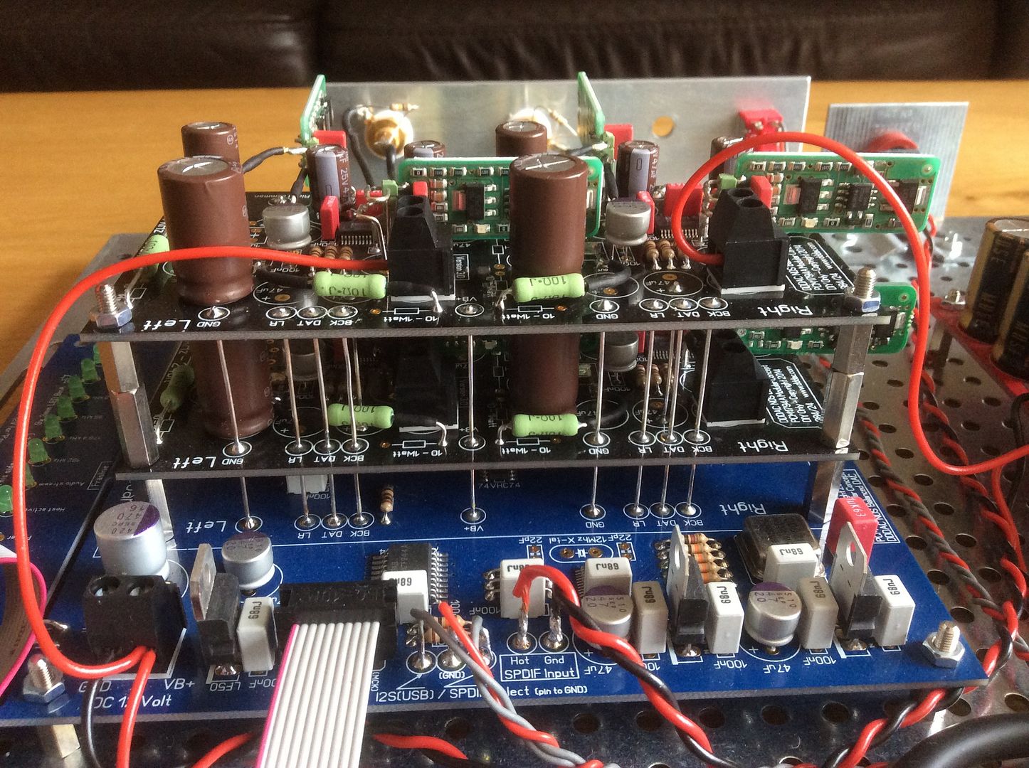
My tweaked single board with buffer and cinemags is sounding wonderful right now.
Next dddac adventure for me will be to use the botic driver for bbb to output 2 channels of right justified data so I can connect my reclocker direct to each channel of the dac deck without needing to use the main board and its shift registers. But for that I need to find some spare time..
Since I sorted my grounding out, I've dialed in the dc offset to be less than 1mV between each pair of buffer outputs and it's totally stable.
My tweaked single board with buffer and cinemags is sounding wonderful right now.
Next dddac adventure for me will be to use the botic driver for bbb to output 2 channels of right justified data so I can connect my reclocker direct to each channel of the dac deck without needing to use the main board and its shift registers. But for that I need to find some spare time..
Finally found some time to add the second DAC module. It sounds truly amazing and still more mods to be applied 8)


I connected the oscilloscope last night... the measurements clearly have shown (as Doede suggested long time ago) the need for little filter capacitors across DAC outputs.
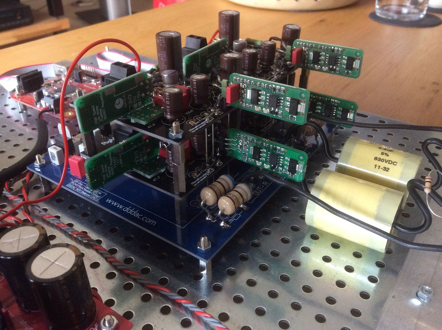
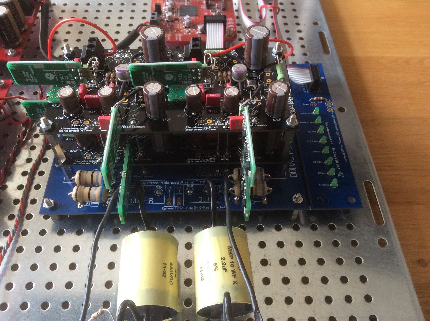
With 4 decker version, I had best results with 4 X 0.01uF, each installed across Apos and Aneg, and Bpos and Bneg on both channels. These values will get rid-off all nasties, while providing negligible attenuation at 20kHz. For those really pedantic ones amongst us, the minimal attenuation at high frequencies can be compensated for in JRiver parametric equalizer. In fact, the curve can be adjusted to be perfectly flat from 20Hz - 20kHz.
The best place to solder capacitors is in fact on the top deck, i.e. not on the motherboard -> the attenuation of (what looked pretty bad on the oscilloscope) oscillations is much better if the caps are installed at the top deck, compared with the (0.01uF X 2) per each channel installed on the motherboard.
Nick
Last edited:
Hi Nick,
Are you talking about the noise which sounds like an air leak in a car tyre?
I tried the filter caps myself a while ago and thought they didn't make much difference. In fact if anything they changed the timbre of the hiss to a harsher tone.
Having examined them tonight I find they are fitted across (a pos)>(b pos) & (a neg)>(b neg).
According to your post I should change them over. Is that right?
I was checking the 20kHz sinewave at 1V RMS / 1.4 V pp. It looked quite bad, with bad ringing on top of each "flat" sample, independent of loading and power supplies. I got nice and smooth results with negligible drop (of 20mV at 20kHz) with capacitors soldered on the top deck (top DAC PCB), between Apos and Aneg and Bpos and Bneg. I suppose this should be clear now - I can take the photo if you are unsure what I'm saying above.
The sound is better as well.
Nick
The sound is better as well.
Nick
Hi Ross, I tried to send you a pm but it seems you "cannot accept further messages until you clear some space".
Jan
Jan
I installed the caps across pos and neg, and the effect was an immediate tightening of the sound. I hope someone can confirm this, as I have learned to be extremely wary of autosuggestion🙂
OK I just removed the caps and put them (a pos)>(a neg) / (b pos)>(b neg) as suggested.
Maybe I don't have noise problem after all, as I cannot be sure it has made any difference.
The caps I am using are Wima 4.7nF and I have a single deck DDDAC. Are those even the correct caps for this application?
Maybe I don't have noise problem after all, as I cannot be sure it has made any difference.
The caps I am using are Wima 4.7nF and I have a single deck DDDAC. Are those even the correct caps for this application?
Finally found some time to add the second DAC module. It sounds truly amazing and still more mods to be applied 8)
Hi Simon,
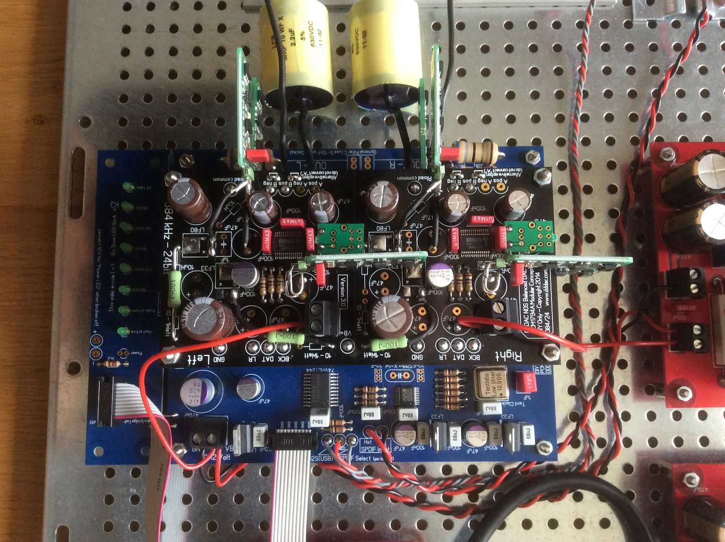
Could you please tell me what type / brand are those green resistors in series with +12V on DAC modules, and what type is that 470uF / 16V DC capacitor on the main board?
Thanks,
Nick
- Home
- Source & Line
- Digital Line Level
- Upgraded Single Board PCM1794 NOS DDDAC