Thanks. I know about different gate resistors. 2 pairs to reduce distortion under low-impedance load. The rest can be taken into account when designing a printed circuit board. And it was just a sketch.
off:How are you doing with the device ?
off:How are you doing with the device ?
I'm still working on aluminum chassis...
v-belt on my mini milling machine broke, and I'm waiting for a new one 🙁
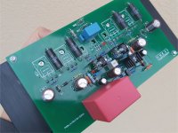
Boards for both channels were built and successfully tested, so I expect no
surprises in the final assembly. I guess it's gonna be another 2 weeks before it's finished (assuming v-belt arrives soon).
===============
Я все еще работаю над алюминиевым шасси ... На моем мини-фрезере сломался клиновой ремень, и я жду новый.
Платы для обоих каналов были созданы и успешно протестированы, поэтому я не ожидаю сюрпризы в финальной сборке. Я думаю, что до его завершения осталось еще 2 недели (при условии, что скоро прибудет клиновой ремень).
v-belt on my mini milling machine broke, and I'm waiting for a new one 🙁
Boards for both channels were built and successfully tested, so I expect no
surprises in the final assembly. I guess it's gonna be another 2 weeks before it's finished (assuming v-belt arrives soon).
===============
Я все еще работаю над алюминиевым шасси ... На моем мини-фрезере сломался клиновой ремень, и я жду новый.
Платы для обоих каналов были созданы и успешно протестированы, поэтому я не ожидаю сюрпризы в финальной сборке. Я думаю, что до его завершения осталось еще 2 недели (при условии, что скоро прибудет клиновой ремень).
Last edited:
The scheme is interesting to look atSince there are too many possibilities to put the Wiederhold VAS into practice, I decided to build it in the simplest form first. Kletzov / Zaichenko VHEX +. The sound is much better than most traditional amps, very clear and smooth.
The scheme is interesting to look at
Attachments

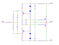
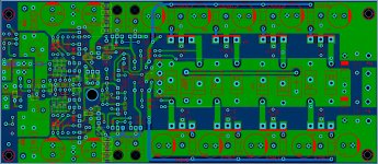
@Maxim. What do you think about the layout below? Wiederhold principle extended to output. LATFETs driven by controlled, bootstrapped CCS'.
Attachments
Last edited:
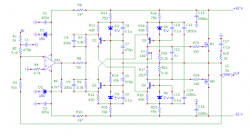
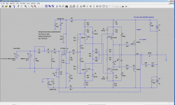
Practical solution from vegalab. I never seen any similar before.
Someone who built it wrote about his measurements. "A 20 kHz square wave is ideal (the square waves before and after the amplifier are identical). At 80 kHz, the rise time is slightly longer and is estimated about 70-100 nanoseconds. The noise is about - 145 - 150 dB, the distortion in the second harmonic is 120 dB, the fourth harmonic is about 130. The odd ones are not visible." Some say it sounds better than BBC-2011
Someone who built it wrote about his measurements. "A 20 kHz square wave is ideal (the square waves before and after the amplifier are identical). At 80 kHz, the rise time is slightly longer and is estimated about 70-100 nanoseconds. The noise is about - 145 - 150 dB, the distortion in the second harmonic is 120 dB, the fourth harmonic is about 130. The odd ones are not visible." Some say it sounds better than BBC-2011
Attachments
Last edited:
It's not Kletsov. Kletsov's feature is in the complete absence of cascades with a common emitter@Maxim. What do you think about the layout below? Wiederhold principle extended to output. LATFETs driven by controlled, bootstrapped CCS'.
Has the right to life.@Maxim. What do you think about the layout below? Wiederhold principle extended to output. LATFETs driven by controlled, bootstrapped CCS'.
an excellent amplifier.But it does not exceed the ones described above in the topic. one level approximatelyPractical solution from vegalab. I never seen any similar before.
Someone who built it wrote about his measurements. "A 20 kHz square wave is ideal (the square waves before and after the amplifier are identical). At 80 kHz, the rise time is slightly longer and is estimated about 70-100 nanoseconds. The noise is about - 145 - 150 dB, the distortion in the second harmonic is 120 dB, the fourth harmonic is about 130. The odd ones are not visible." Some say it sounds better than BBC-2011
an excellent amplifier.But it does not exceed the ones described above in the topic. one level approximately
Right, but it's much simpler, and very fast.
😀Right, but it's much simpler, and very fast.
The printed circuit board is easier to make without errors
Last edited:
😀
The printed circuit board is easier to make without errors
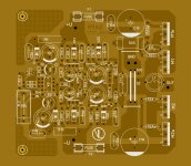
Some use this PCB, but it's worth to design a common PCB with power supply, avoiding wiring problems. After VHEX will fully completed, maybe I'll build this (LES-7777). It's an impressive circuit, has very low parasitic capacitance issues in a whole circuit results clean, smooth and natural sound. And pretty "unusual" ... as the title of this thread suggests.
Attachments
Last edited:
I prefer a different topology. And greater loop gainAnd pretty "unusual" ... as the title of this thread suggests.
Attachments
Practical solution from vegalab. I never seen any similar before.
Here is quick sim.
As is, square waves are definitely not optimized (yet).
FFT and Thd profiles are relatively good (compared for instance with VHex), but far from being 'the best' in this thread.
More work is needed, especially for getting better square waves.
Also, doesn't look particularly fast, judging from the speed of (distorted) square waves.
Still, may sound better than BBC-2011.. We can only dispute measurements or sims, not individual's opinions..
Attachments
Last edited:
Wow. That was fast. Thank you. BTW Q1 and Q2 run with higher currents than the drivers of FETs. So can be replaced the 2N BJTs with 2SA/2SCs as can be seen in original layout.
I wouldn't bother much with a high build-up rate.It is necessary to find a compromise between the slew rate, low distortion and high overload capacity.
The opinion of an amateur, not a pro.
The opinion of an amateur, not a pro.
1) Q1/Q2 run at 20mW
2) drivers run at 260mW - these can't be small transistors. they are only good up to 80mW
Instead of looking at currents, look at power (just move mouse over the transistor, bottom status will show power dissipation).
My sim is at higher rail voltage than original.
Well, technically Q3/Q4 are not drivers.. 2nd cascode? Whatever the correct name is....
Last edited:
- Home
- Amplifiers
- Solid State
- Unusual amp from 1987