Tried the following op-amps with NO success:
LT1056, LF356, TLE2071, TLE2081, LT1357, OPA134, LT1360
This amp, as is, works only with TL071.
For different op-amps, it will need different compensation, and more experiments.
After trying all these op-amps, I was kind of surprised to see it actually working again after I put TL071 back 🙂
I'm surprised that TLE2071, TLE2081 didn't work.
I thought they are supposed to be drop-in replacements for TL071.
I wonder how Prohodimez's version did work, given the changes he made, without (as far as I can tell) even using
oscilloscope?
Prohodimez, if you have some lottery numbers to suggest for the next game, please post them here 🙂
==========
Пробовал следующие операционные усилители безуспешно:
LT1056, LF356, TLE2071, TLE2081, LT1357, OPA134, LT1360
Этот усилитель как есть работает только с TL071.
Для разных операционных усилителей потребуется разная компенсация и дополнительные эксперименты.
Попробовав все эти операционные усилители, я был немного удивлен, увидев, что они снова работают после того, как я вернул TL071.
Удивлен, что TLE2071, TLE2081 не работали. Я думал, что они должны быть заменой TL071.
Интересно, как работала версия Проходимеза с учетом внесенных им изменений без (насколько я могу судить) даже использования осциллограф?
Проходимез, если у вас есть лотерейные номера для следующей игры, разместите их здесь 🙂
LT1056, LF356, TLE2071, TLE2081, LT1357, OPA134, LT1360
This amp, as is, works only with TL071.
For different op-amps, it will need different compensation, and more experiments.
After trying all these op-amps, I was kind of surprised to see it actually working again after I put TL071 back 🙂
I'm surprised that TLE2071, TLE2081 didn't work.
I thought they are supposed to be drop-in replacements for TL071.
I wonder how Prohodimez's version did work, given the changes he made, without (as far as I can tell) even using
oscilloscope?
Prohodimez, if you have some lottery numbers to suggest for the next game, please post them here 🙂
==========
Пробовал следующие операционные усилители безуспешно:
LT1056, LF356, TLE2071, TLE2081, LT1357, OPA134, LT1360
Этот усилитель как есть работает только с TL071.
Для разных операционных усилителей потребуется разная компенсация и дополнительные эксперименты.
Попробовав все эти операционные усилители, я был немного удивлен, увидев, что они снова работают после того, как я вернул TL071.
Удивлен, что TLE2071, TLE2081 не работали. Я думал, что они должны быть заменой TL071.
Интересно, как работала версия Проходимеза с учетом внесенных им изменений без (насколько я могу судить) даже использования осциллограф?
Проходимез, если у вас есть лотерейные номера для следующей игры, разместите их здесь 🙂
Last edited:
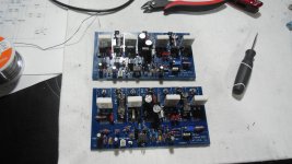
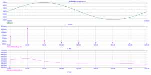
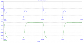
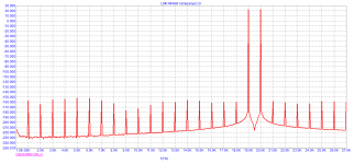
I didn't play music. Only signal generator and oscilloscope.
After I'm done with 2nd channel, I'll put both of them on the chassis/heatsink, use my proper PSU (not switching, but linear (with toroidal transformer)), and then test the music on proper speakers, with protection, good quality source, etc..
===========
Я не играл музыку. Только генератор сигналов и осциллограф. После того, как я закончу со 2-м каналом, я помещаю их оба на шасси / радиатор, использую свой правильный блок питания (не переключающийся, а линейный (с тороидальным трансформатором)), а затем тестирую музыку.
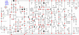
I'm sure it's just the matter of adjusting C8 or C16..maybe the throttle will allow other op-amps to be used?
Since you are going to use different op-amp, different output, different rail voltage, you are going to go through
all of this testing/adjusting one more time 🙂
We should have video link to watch this process 🙂
========
Поскольку вы собираетесь использовать другой операционный усилитель, другой выход, другое напряжение шины, вы собираетесь пройти через все это тестирование / настройка еще раз 🙂 У нас должна быть ссылка на видео, чтобы наблюдать за этим процессом 🙂
Last edited:
Холодно у нас.I'm sure it's just the matter of adjusting C8 or C16..
Since you are going to use different op-amp, different output, different rail voltage, you are going to go through
all of this testing/adjusting one more time 🙂
We should have video link to watch this process 🙂
====================
I'm going to launch another monster right now . Let it get a little warmer, because it's too cold here. Monoblocks are soldered on the table, it is necessary to run through the oscilloscope
Only -9 degrees, that's not too bad 🙂 Here today was sunny and +8 degrees.
Good luck with monster.
Good luck with monster.
It's only warm tonight. -11 total. Was -22-27 for two weeks .Only -9 degrees, that's not too bad 🙂 Here today was sunny and +8 degrees.
Good luck with monster.

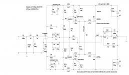
Reduced the number of active elements and applied ECW20P20/ECW20N20.It did not require a two-level power supply, just + / - 40 volts.The correction elements are set to the minimum of stability.
Attachments

Last edited:
"to maximum stability", I guess?
Rather, the minimum below which it is impossible to reduce the values of the correction elements. And so everything will depend on the specific installation. You can also increase the values of the correction elements. But I wanted to know the lower limit of stability.The limit for this solution. To further reduce the level of all possible distortions, it is necessary to complicate the scheme and introduce an additional opamp
Attachments
Last edited:
These are dual-die mosfets, with internal source resistors, so:
1) most likely you don't need source resistors in your schematic
2) at 40V rails, you most likely only need 1 pair of devices.
With 2 pairs of dual-die mosfets, they not gonna run at full power capacity
=======================
Это МОП-транзисторы с двумя матрицами и внутренними резисторами источника, поэтому: 1) скорее всего, вам не нужны исходные резисторы в вашей схеме 2) на рейках 40В вам, скорее всего, понадобится всего 1 пара устройств. С двумя парами МОП-транзисторов с двумя матрицами они не будут работать на полную мощность
Last edited:
Also, input capacitances of P devices differs (a lot) from input capacitance of N devices, so either:
a) add extra caps to N device to balance things
b) use different value for gate resistors to keep it stable.
With same gate resistors and without extra caps on N devices, they are more likely to oscillate.
Have a look at my Wiederhold LatFet build (I used original 2SJ162/2SK1058 in that build)
Unusual amp from 1987
========== Example
Exicons single die: does not requires GS capacitor. P/N have the same capacitance.
Exicon double die: N device reqires 900p extra cap at GS. P/N have different capacitance.
Renesas/NEC:
2SJ162/2SK1058: N device (2SK1058) requires 150pF extra cap at GS.
P/N have different capacitance.
Gate protection diodes are not required here. Included in the transistor (all latfets have them).
Alternative to adding capacitor to N device: different gate stoppers.
Let's say the 2SJ162 has a gate stopper of 100 Ohm and a gate
capacitance of 900pF, the RC time constant is just RgatexCgate=RC time constant,
so 100x900x10^-12=90nS. If we want 'balance' we need a resistance on the gate of
the 2SK1058 that gives the same time constant.
So, Rgate x 600pF = 90nS, solve for Rgate. In this case Rgate needs to be 150 Ohm.
Last edited:
- Home
- Amplifiers
- Solid State
- Unusual amp from 1987