For now, the biggest problem is the latching of the op-amp.
I'm sure stability/oscillations issues can be resolved with careful adjustment of few caps/resistors once latching is taken care of.
Will try the Shottky's..
=====
На данный момент самая большая проблема - это защелкивание операционного усилителя.
Я уверен, что проблемы со стабильностью / колебаниями могут быть решены путем тщательной регулировки нескольких конденсаторов / резисторов после того, как позаботится о фиксации.
Попробую Шоттки ..
I tried to fix op-amp latching: added 2 BAT43 (didn't have BAT54) between the input of the op-amp and the ground.
It helped, but didn't fix the problem completely.
At least the amp can start with load connected.
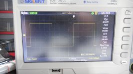
Square waves, with load connected look clean.
Clipping (upper part of sinus, 1kHz - 5kHz) happens at 56Vpp, like before; I think it's my PSU running out of juice...
So it's a progress.
Now, the problems:
1) If signal is present on the input, amp will not start correctly, op-amp will latch. 10V at the output of the op-amp. Negative rail will sag to -9V. Usual symptoms.
2) If op-amp latched, the next restart (power on) has to be done after a while, until some discharging happens (within the op-amp?). Otherwise, on the next restart (power on) the amp will latch right away.
3) If signal is not present (yet) on the input, it will start fine, and behaves ok, until:
a) I keep increasing amplitude of input signal, reach 56Vpp (for sinus, for squares it happens sooner) at the output, my PSU will run out of juice, and op-amp will latch-up.
OR
b) I disrupt the amp somehow, e.g. disconnecting input, trying to measure voltage somewhere on the pcb, etc...
So the bottom line, that op-amp is still latching-up
(operational amplifier - Op amp - symptoms of latchup? - Electrical Engineering Stack Exchange)
Questions are:
1) why?
2) how to prevent this?
=======
Я попытался исправить фиксацию операционного усилителя: добавил 2 BAT43 (не было BAT54) между входом операционного усилителя и землей.
Это помогло, но не устранило проблему полностью. По крайней мере, усилитель может запуститься с подключенной нагрузкой. Прямоугольные волны при подключенной нагрузке выглядят чистыми.
Ограничение (верхняя часть синуса, 1 кГц - 5 кГц) происходит при 56Vpp, как и раньше; Думаю, у моего БП кончается сок ...
Так что это прогресс.
Теперь о проблемах:
1) Если сигнал присутствует на входе, усилитель запускается неправильно, операционный усилитель фиксируется. 10В на выходе ОУ. Минусовая шина просядет до -9В. Обычные симптомы.
2) Если операционный усилитель заблокирован, следующий перезапуск (включение) должен быть выполнен через некоторое время, пока не произойдет разрядка (внутри операционного усилителя?). В противном случае при следующем перезапуске (включении) усилитель сразу зафиксируется.
3) Если сигнал на входе отсутствует (пока), он будет нормально запускаться и вести себя нормально, пока:
а) Я продолжаю увеличивать амплитуду входного сигнала, достигая 56Vpp (для синуса, для квадратов это происходит раньше) на выходе, в моем блоке питания кончится заряд, и операционный усилитель заблокируется.
ИЛИ ЖЕ
б) Я каким-то образом нарушаю работу усилителя, например отключение входа, попытка измерить напряжение где-нибудь на плате и т. д.
Итак, суть в том, что операционный усилитель все еще работает. (operational amplifier - Op amp - symptoms of latchup? - Electrical Engineering Stack Exchange)
Вопросы такие:
1) почему?
2) как этого избежать?
It helped, but didn't fix the problem completely.
At least the amp can start with load connected.
Square waves, with load connected look clean.
Clipping (upper part of sinus, 1kHz - 5kHz) happens at 56Vpp, like before; I think it's my PSU running out of juice...
So it's a progress.
Now, the problems:
1) If signal is present on the input, amp will not start correctly, op-amp will latch. 10V at the output of the op-amp. Negative rail will sag to -9V. Usual symptoms.
2) If op-amp latched, the next restart (power on) has to be done after a while, until some discharging happens (within the op-amp?). Otherwise, on the next restart (power on) the amp will latch right away.
3) If signal is not present (yet) on the input, it will start fine, and behaves ok, until:
a) I keep increasing amplitude of input signal, reach 56Vpp (for sinus, for squares it happens sooner) at the output, my PSU will run out of juice, and op-amp will latch-up.
OR
b) I disrupt the amp somehow, e.g. disconnecting input, trying to measure voltage somewhere on the pcb, etc...
So the bottom line, that op-amp is still latching-up
(operational amplifier - Op amp - symptoms of latchup? - Electrical Engineering Stack Exchange)
Questions are:
1) why?
2) how to prevent this?
=======
Я попытался исправить фиксацию операционного усилителя: добавил 2 BAT43 (не было BAT54) между входом операционного усилителя и землей.
Это помогло, но не устранило проблему полностью. По крайней мере, усилитель может запуститься с подключенной нагрузкой. Прямоугольные волны при подключенной нагрузке выглядят чистыми.
Ограничение (верхняя часть синуса, 1 кГц - 5 кГц) происходит при 56Vpp, как и раньше; Думаю, у моего БП кончается сок ...
Так что это прогресс.
Теперь о проблемах:
1) Если сигнал присутствует на входе, усилитель запускается неправильно, операционный усилитель фиксируется. 10В на выходе ОУ. Минусовая шина просядет до -9В. Обычные симптомы.
2) Если операционный усилитель заблокирован, следующий перезапуск (включение) должен быть выполнен через некоторое время, пока не произойдет разрядка (внутри операционного усилителя?). В противном случае при следующем перезапуске (включении) усилитель сразу зафиксируется.
3) Если сигнал на входе отсутствует (пока), он будет нормально запускаться и вести себя нормально, пока:
а) Я продолжаю увеличивать амплитуду входного сигнала, достигая 56Vpp (для синуса, для квадратов это происходит раньше) на выходе, в моем блоке питания кончится заряд, и операционный усилитель заблокируется.
ИЛИ ЖЕ
б) Я каким-то образом нарушаю работу усилителя, например отключение входа, попытка измерить напряжение где-нибудь на плате и т. д.
Итак, суть в том, что операционный усилитель все еще работает. (operational amplifier - Op amp - symptoms of latchup? - Electrical Engineering Stack Exchange)
Вопросы такие:
1) почему?
2) как этого избежать?
Last edited:
1. Change the OOS with T-OOS.2. Reduce the gain at high frequencies.That is, go to the throttle in correction.3. Diode limiter at the input of the operational amplifier, as shown in the figure.4, The loop gain is very large.That's why the problem arose.
Attachments
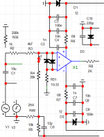
from 5 to 47 ohms any, although you can do without it.
The mouse died on the computer.I need to buy a new one tomorrow. I can't model it yet.
R51 added to introduce a different anti-clip. But it is difficult to debug it without a mouse. don't move the parts.
The mouse died on the computer.I need to buy a new one tomorrow. I can't model it yet.
R51 added to introduce a different anti-clip. But it is difficult to debug it without a mouse. don't move the parts.
Last edited:
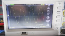
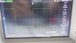
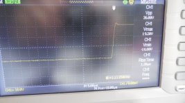
Ok, after latest changes amp is very stable.
No oscillations (well, maybe small ones..), no op-amp latch-up.
Stable bias at 50mA. Cold Zobel. Rise time 1.6us.
Didn't reach clipping yet, at 66Vpp was still going strong.
Square waves have small over-shots; this will have to be taken care of.
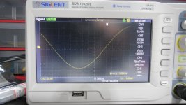
When I look closer, sinus waves possibly have very small oscillations - will zoom them tomorrow to confirm.
Not sure if this is an image artifact or actual oscillation.
All of these tests were only with 1kHz, tomorrow will test more.
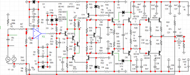
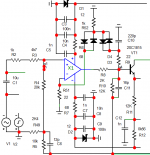
Attached current schematic (as built), and sim file.
==========================
Хорошо, после последних изменений усилитель очень стабилен.
Без колебаний, без фиксации операционного усилителя.
Стабильное смещение при 50 мА. Холодный Зобель.
Время нарастания 1.6us.
Еще не дошел до отсечения, на 66Vpp все еще было хорошо.
Прямоугольные волны имеют небольшие перевыпуски; об этом нужно будет позаботиться.
Когда я приглядываюсь поближе, синусовые волны, возможно, имеют очень небольшие колебания - завтра увеличу их, чтобы подтвердить.
Все эти тесты были только с 1кГц, завтра тестирую еще.
Прикрепленная текущая схема (как построенная) и sim-файл.
No oscillations (well, maybe small ones..), no op-amp latch-up.
Stable bias at 50mA. Cold Zobel. Rise time 1.6us.
Didn't reach clipping yet, at 66Vpp was still going strong.
Square waves have small over-shots; this will have to be taken care of.
When I look closer, sinus waves possibly have very small oscillations - will zoom them tomorrow to confirm.
Not sure if this is an image artifact or actual oscillation.
All of these tests were only with 1kHz, tomorrow will test more.
Attached current schematic (as built), and sim file.
==========================
Хорошо, после последних изменений усилитель очень стабилен.
Без колебаний, без фиксации операционного усилителя.
Стабильное смещение при 50 мА. Холодный Зобель.
Время нарастания 1.6us.
Еще не дошел до отсечения, на 66Vpp все еще было хорошо.
Прямоугольные волны имеют небольшие перевыпуски; об этом нужно будет позаботиться.
Когда я приглядываюсь поближе, синусовые волны, возможно, имеют очень небольшие колебания - завтра увеличу их, чтобы подтвердить.
Все эти тесты были только с 1кГц, завтра тестирую еще.
Прикрепленная текущая схема (как построенная) и sim-файл.
Attachments

Last edited:
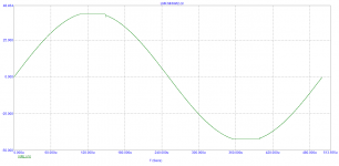
I didn't sim square waves after latest changes; now I see that square waves need fixing.
With Cc=47pF (instead of 120pF as in the actual build), they should be much better...
R16 in actual build is 4k7, and idle pot is 500 Ohm. This doesn't match the sim, I guess my BD139 model doesn't match
the real device.
Update: with C16=18pF, C8=6pF, Cc=22p square waves should be OK.
Will try tomorrow
Also, clipping behavior needs to be improved.
Attachments
Last edited:
Although some fellow specialists scolded me for using T-oos,but with it, the amplifiers are much more stable.
Yes, there was a dispute on one site in the Russian Federation.Who?
In the meantime, the new anti-clip should finally solve all the problems.There is an outlier, but it has become much smaller
Well, it remains to introduce an inductive correction
Attachments
Last edited:
Looks like for real amp, will need a new PCB...
Without new clip, I managed to use existing pcb: 2 diodes added on the top side (with new holes), and 2 resistors under pcb...
Without new clip, I managed to use existing pcb: 2 diodes added on the top side (with new holes), and 2 resistors under pcb...
There's not much point in changing the anti-clip. You not listen at maximum power and the old anti-clip will be quite good .
Last edited:
>Update: with C16=18pF, C8=6pF, Cc=22p square waves should be OK.
These values don't work. Will keep testing.
The sim doesn't agree with actual amp..
The one that worked in the prototype (with square waves with small over-shots)
were C16=12pF, C8=12pF, Cc=120p.
These values don't work. Will keep testing.
The sim doesn't agree with actual amp..
The one that worked in the prototype (with square waves with small over-shots)
were C16=12pF, C8=12pF, Cc=120p.
Last edited:
I was experimenting with different values for C16/C8,
with Cc below 100pF (22p, 47p, 68p).
One conclusion so far: Cc must be at least 100pF.
In the sim Cc=22pF was enough....
So I'm back to Cc=120pF, next - will try to modify C8/C16.
There are 2 problems to solve:
1) small overshot in square waves
2) small oscillation in sinus 1kHz (at bottom peak) when close to clipping.
This is visible only in low Freq (1KHz). Not visible at 20kHz.
3) There is no other oscillations visible, only screen artifacts.
Tested sinus up to 100kHz.
Tested square waves at 1kHz, 10kHz, 30kHz, 50kHz.
Almost perfect at all frequencies, rise time at high Vpp out (40V if I remember correctly), was around 900ns. So slew rate is OK.
Because of the square waves, the amp got red hot, so will take a break to let it cool down 🙂
=====================
Я экспериментировал с разными значениями для C16 / C8, с Cc ниже 100 пФ (22p, 47p, 68p).
Вывод пока один: Cc должна быть не менее 100 пФ.
В симе хватило Cc = 22pF ....
Итак, я вернулся к Cc = 120pF, дальше - попробую доработать C8 / C16.
Необходимо решить 2 проблемы:
1) небольшой промах в виде прямоугольных волн
2) небольшие колебания в синусе 1 кГц (нижний пик) при близком к клиппированию.
Это видно только при низкой частоте (1 кГц). Не отображается на частоте 20 кГц.
3) Других колебаний не видно, только артефакты экрана. Протестировал синус до 100кГц.
Протестированы прямоугольные волны на частотах 1 кГц, 10 кГц, 30 кГц, 50 кГц.
Практически идеально на всех частотах, время нарастания при высоком выходном напряжении (40 В, если я правильно помню) было около 900 нс.
Так что скорость нарастания в порядке.
Из-за прямоугольных волн усилитель стал раскаленным, поэтому сделаем перерыв, чтобы дать ему остыть.
Attachments
-
 DSCN0470.JPG236.9 KB · Views: 3,625
 -
 DSCN0469.JPG239 KB · Views: 3,506
 -
 DSCN0467.JPG238.5 KB · Views: 3,525
 -
 DSCN0465.JPG225 KB · Views: 3,675
 -
 DSCN0464.JPG236.8 KB · Views: 3,672
 -
 DSCN0463.JPG237 KB · Views: 3,632
 -
 DSCN0462.JPG249.3 KB · Views: 3,577
 -
 DSCN0460.JPG228.5 KB · Views: 3,691
 -
 DSCN0459.JPG245.3 KB · Views: 3,475
 -
 DSCN0456.JPG232 KB · Views: 3,593
Last edited:
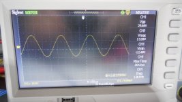
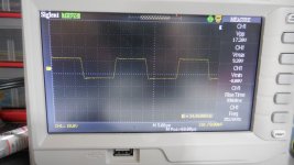
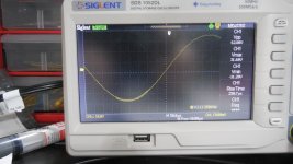
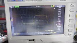
All screenshots done with load 8 Ohm, rails 45V, idle current 50mA per transistor.
Output offset 1mV, stable.
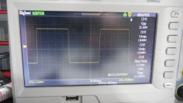
The last screen - 100kHz square wave at 14Vpp - made the heatsink and laod resistor red hot, but the amp took it 🙂
Can't reach the clip on the sinus wave, as my lab PSU doesn't provide enough current, and it goes into OFF state..
======
Все скриншоты сделаны при нагрузке 8 Ом, шинах 45В, токе холостого хода 50мА на транзистор. Смещение выхода 1 мВ, стабильно. Последний экран - прямоугольная волна 100 кГц при 14Vpp - раскалил радиатор и резистор, но усилитель это принял. Не могу дотянуться до зажима синусовой волны, так как мой лабораторный блок питания не обеспечивает достаточного тока и переходит в состояние ВЫКЛ.
Output offset 1mV, stable.
The last screen - 100kHz square wave at 14Vpp - made the heatsink and laod resistor red hot, but the amp took it 🙂
Can't reach the clip on the sinus wave, as my lab PSU doesn't provide enough current, and it goes into OFF state..
======
Все скриншоты сделаны при нагрузке 8 Ом, шинах 45В, токе холостого хода 50мА на транзистор. Смещение выхода 1 мВ, стабильно. Последний экран - прямоугольная волна 100 кГц при 14Vpp - раскалил радиатор и резистор, но усилитель это принял. Не могу дотянуться до зажима синусовой волны, так как мой лабораторный блок питания не обеспечивает достаточного тока и переходит в состояние ВЫКЛ.
Last edited:
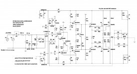
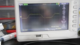
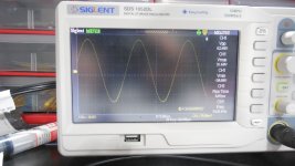
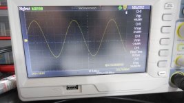
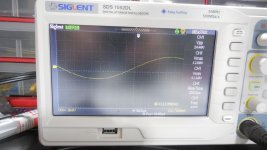
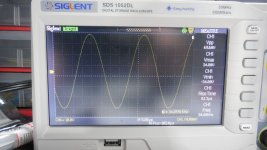
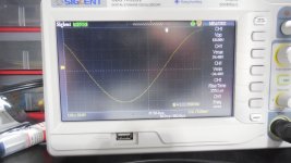
OK, the amp is rock solid with these values:
C16=20p, C8=10p, C7=200p, C10=470p, Cc=120p
R31=10k, R9=18k, R20=3
op-amp: TL071
All waves look good, overshot in squares is gone, oscillation in lower sinus close to clip is gone.
C16=20p, C8=10p, C7=200p, C10=470p, Cc=120p
R31=10k, R9=18k, R20=3
op-amp: TL071
All waves look good, overshot in squares is gone, oscillation in lower sinus close to clip is gone.
Attachments
-
 sin_1k_69v.JPG232.6 KB · Views: 3,775
 -
 sin_34k_69v.JPG250.8 KB · Views: 3,545
 -
 sin_100k.JPG228.5 KB · Views: 3,537
 -
 sin34k_48v.JPG235.2 KB · Views: 3,506
 -
 sin_1k_68v.JPG235.4 KB · Views: 3,705
 -
 s_44k.JPG240.7 KB · Views: 3,686
 -
 s_10k.JPG239.7 KB · Views: 3,509
 -
 s_1k.JPG234.9 KB · Views: 3,489
 -
 DSCN0473.JPG250.9 KB · Views: 3,407
 -
 DSCN0472.JPG227.5 KB · Views: 3,484
Last edited:
Current LTSpice sim file (as built)
Attachments
Last edited:
- Home
- Amplifiers
- Solid State
- Unusual amp from 1987