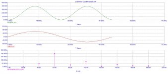
I checked simulations of many other hexfet quasi amps, and it seems that this asymmetry in upper/lower devices conducting is normal.
Lower device always has sharp 0V crossing, and upper device more rounded.
Tomorrow will check if BJT quasi amps also behave like that?
These changes that Steve made (LEDs), actually look like they are improving things (smoother crossover).
Lower device always has sharp 0V crossing, and upper device more rounded.
Tomorrow will check if BJT quasi amps also behave like that?
These changes that Steve made (LEDs), actually look like they are improving things (smoother crossover).
Finally I got the DIN=>RCA cable, and was able to properly hook up
new amp for testing - Wiederhold77 BJT Quasi (2N3055 version) described in posts #952 and #985.
Surprise 🙂 - can't tell the sound from any other Wiederhold77 tested (LatFet, HexFet Quasi).
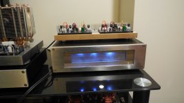
Sounds great. A lot of bass, and very clear sound. Runs cold, not much heatsinking needed (I use 20V rails from my Class A amp PSU (small alu box on the left)).
Heatsinks you see in the photos are overkill, but didn't have anything smaller. I guess these emitter resistors (5W) are also too big, 2W would be enough.
But - doesn't feel weaker than his bigger brothers at all, even though max power with 25V rails will barely exceed 30W RMS (and 50W peak power).
Cost of output transistors - 70 cents each (8 in total for 2 channels), and it sounds the same as expensive Exicon latfets.
Must be something wrong with my ears, but I will risk a statement that this must be the best 2N3055 amp ever built 🙂
new amp for testing - Wiederhold77 BJT Quasi (2N3055 version) described in posts #952 and #985.
Surprise 🙂 - can't tell the sound from any other Wiederhold77 tested (LatFet, HexFet Quasi).
Sounds great. A lot of bass, and very clear sound. Runs cold, not much heatsinking needed (I use 20V rails from my Class A amp PSU (small alu box on the left)).
Heatsinks you see in the photos are overkill, but didn't have anything smaller. I guess these emitter resistors (5W) are also too big, 2W would be enough.
But - doesn't feel weaker than his bigger brothers at all, even though max power with 25V rails will barely exceed 30W RMS (and 50W peak power).
Cost of output transistors - 70 cents each (8 in total for 2 channels), and it sounds the same as expensive Exicon latfets.
Must be something wrong with my ears, but I will risk a statement that this must be the best 2N3055 amp ever built 🙂
Attachments

Last edited:
Ничего страшного , я не спал.Sorry to wake you up 🙂
=============
Извините, что разбудил вас 🙂
Great. Good news is like a balm to the soul .
On my forum, look at the latest schemes..
Last edited:
Why do you call it "composite"?
What does it mean?
=================
Почему вы называете это «составным»? Что это означает?
What does it mean?
=================
Почему вы называете это «составным»? Что это означает?
No, here the joint operation of the LF357 and AD825 (544UD2) / 1mA quiescent current of the output transistors.Like this one, that I built while ago:
EZ-Dump: dump your current without really trying
Although they are similar.But I have a deep OOS correction .And the signal comes from the opamp power buses
Last edited:
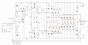
I recalculated to 200 watts at a load resistance of 8 ohms. At the request of one of our colleagues.
Attachments
Last edited:
A monster. With all protection and anti-clipnice!
It was necessary to parallelize Q8/Q9.
Last edited:
Looks like you don't like Mosfet transistors in the output?
Especially without protection 🙂
Especially without protection 🙂
Attachments
Last edited:
Hi, Mr.Minek. Happy New Year!
I have a few questions for you.

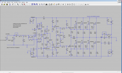
How do I turn on the ground, according to scheme #1078. Signal or power GND? Marked in red.


The next question. Maybe it would be more correct to make changes according to the attached scheme, in the recalculation of the values of the resistor R?.
I have a few questions for you.
How do I turn on the ground, according to scheme #1078. Signal or power GND? Marked in red.
The next question. Maybe it would be more correct to make changes according to the attached scheme, in the recalculation of the values of the resistor R?.
- Home
- Amplifiers
- Solid State
- Unusual amp from 1987