Ничего не надо пересчитывать, просто соедините токозадающие резисторы между собой.
Nothing needs to be recalculated, just connect the current-setting resistors together.
Nothing needs to be recalculated, just connect the current-setting resistors together.
Hi, Mr. Stanislav. Happy New Year!
I still have a question about connecting the ground. Power or Signal GND by Red Marker.
I still have a question about connecting the ground. Power or Signal GND by Red Marker.
Hi, Mr. Stanislav. Happy New Year!
I still have a question about connecting the ground. Power or Signal GND by Red Marker.
Продублировал бы на родном для нас языке,было бы понятно нам троим.Это значек земля или общий провод.Обозначение в Лтс спайс.
>Maybe it would be more correct to make changes according to the attached scheme, in the recalculation of the values of the resistor R
Current flowing through R (and LEDs) should be 4mA or about.
You can either use 2 resistors, like in the schematic - going to the ground, or one resistor between bases (like I used before) with double value (and double power rating).
Current flowing through R (and LEDs) should be 4mA or about.
You can either use 2 resistors, like in the schematic - going to the ground, or one resistor between bases (like I used before) with double value (and double power rating).
Last edited:
>Power or Signal GND by Red Marker.
R11/R12 should go to Power GND.
Everything except input network (C15, op-amp) should go to Power GND.
R11/R12 should go to Power GND.
Everything except input network (C15, op-amp) should go to Power GND.

>How to connect the GND correctly? Power or signal GND..
Everything except input network (C15, op-amp) should go to Power GND.
Everything except input network (C15, op-amp) should go to Power GND.
Not sure about C7 ground... Maxim, you have an opinion?
Power GND or Signal GND?
On your PCB you have a ground plane, so it's hard to distinguish between input gnd, and power gnd...
Power GND or Signal GND?
On your PCB you have a ground plane, so it's hard to distinguish between input gnd, and power gnd...
Last edited:
Hi, Mr.Minek.

I have several such transistors: Fairchild Power IGBT.


In the attached examples, the replacement takes place without changing the denominations.
Can I also just put these IGBT transistors in your QUASI MLK amplifier?
I have several such transistors: Fairchild Power IGBT.
In the attached examples, the replacement takes place without changing the denominations.
Can I also just put these IGBT transistors in your QUASI MLK amplifier?
>Can I also just put these IGBT transistors in your QUASI MLK amplifier?
Generally speaking - you can, BUT the simulation needs to be done with proper models - if you have them.
Most likely, in case of these amps here in this thread, it will NOT be drop-in replacement.
Some components (feedback, compensation caps, gate stoppers, bias, etc..) will VERY LIKELY need adjustment.
If you can't simulate it, you can build it, and then test-and-try with oscilloscope and a lot of patience. This is definitely not recommended.
In a project like this - building power amplifier - the cost of output devices is really not significant at all. What is it? 10% of the overall cost? Most likely much less than that.
BTW - I suspect there is a reason why nobody uses IGBT transistors in audio amps...
Last edited:
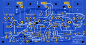
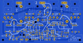
Working on PCBs (one for complementary version and one for quasi)..
Same size as previous Wiederhold77 amps.
Same size as previous Wiederhold77 amps.
Attachments
Last edited:
The power bus impedance should not be reduced? increase the number of electrolytic capacitors and position the power bus more optimally.
>The power bus impedance should not be reduced? increase the number of electrolytic capacitors and position the power bus more optimally.
You are right, but I can't for 2 reasons:
1) space - my metal chassis are not big, and I want to keep them compact
2) some of my PSUs are SMPS, and they can't charge big caps when starting..
All my builds are like this, with 220uF caps on board, and they work fine.
Of course I have big caps in the PSU itself (non SMPS ones).,,

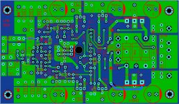
I also developed an experiment board. This will be a separate IPS module. I have doubts about connecting the land (GND). The oscilloscope won't help here, just the headphones.
(pcb).
Somewhere for the Soviet Ampiton-002 amplifier, there is a LMC printed circuit board lying around, I will find it, show it in the sprint.
Somewhere for the Soviet Ampiton-002 amplifier, there is a LMC printed circuit board lying around, I will find it, show it in the sprint.
Attachments
Last edited:

- Home
- Amplifiers
- Solid State
- Unusual amp from 1987