This chtoli.
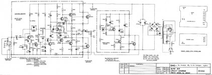
This is something.The output stage is structurally similar to that of Brig 001. The only difference is in the nested oos of Brig 001
This is something.The output stage is structurally similar to that of Brig 001. The only difference is in the nested oos of Brig 001
Attachments
Last edited:
Base resistors >=100 Ohms per BJT output transistor leaves them floating on at 10KHz+ and because it's difficult to cross couple the lower CFP, the easiest solution is to reduce the base resistor. But that is a bit harder (~+50mA) on the PNP driver so a triple means there is more drive for a smaller base resistor. I have played with push-pull drivers in this position but it becomes a tricky tweaking problem prone to instability and distortion. Accidental feedback causing HF oscillation has destroyed a lot of BJT amps because the outputs go into shoot through conduction.
Last edited:
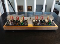
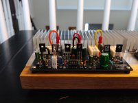
Wiederhold77 BJT Quasi (TIP3055 devices) in the chassis, waiting for music tests 🙂
To stay in the spirit of the era, I didn't put RCA input sockets on it, but
5-pin DIN connector instead; now I have to find my old, misplaced RCA=>DIN cable 🙂
The very first amp I built, back when I was 18, was using 2N3055 devices (Hungarian Tungsram version), and
was still being used in my father's living room last time I checked - after so many years..
Let's see if this one will produce the same sound I remember..
Attachments


Last edited:
Proudly noticed...! 😉...was using 2N3055 devices (Hungarian Tungsram version)...
Hope the new one will be as good as that one!
This is regarding HexFet quasi version of the amp (2 pairs of output dev).
Originally, I set idle current to 40mA per device. Usually that the correct number
for Hexfet amps.
When rechecking things today on the oscilloscope, the sinus wave looked perfect at 1kHz, but at 10kHz I was able to spot slight crossover distortion.
This distortion disappers completely from the scope if I increase idle current to 90mA per device.
Are these numbers consistent with your experience?
Seems kind of high - 90mA per device. There is enough heatsinking, and these
are robust transistors, so it's not a problem, but if this is 'normal', I will have to revisit all my quasi hexfet amps from the past, and check carefully for crossover
distortion at 10kHz and their idle currents.
speed
This is why I'm such a fan of cross coupling. At speed the gate capacitance causes "rectification". But if this is a quasi then that may be difficult. I failed to find a FET quasi in this thread so that I could be more "helpful". post#??
This is regarding HexFet quasi version of the amp (2 pairs of output dev).
Originally, I set idle current to 40mA per device. Usually that the correct number
for Hexfet amps.
When rechecking things today on the oscilloscope, the sinus wave looked perfect at 1kHz, but at 10kHz I was able to spot slight crossover distortion.
This distortion disappers completely from the scope if I increase idle current to 90mA per device.
Are these numbers consistent with your experience?
Seems kind of high - 90mA per device. There is enough heatsinking, and these
are robust transistors, so it's not a problem, but if this is 'normal', I will have to revisit all my quasi hexfet amps from the past, and check carefully for crossover
distortion at 10kHz and their idle currents.
This is why I'm such a fan of cross coupling. At speed the gate capacitance causes "rectification". But if this is a quasi then that may be difficult. I failed to find a FET quasi in this thread so that I could be more "helpful". post#??
Last edited:
https://www.diyaudio.com/forums/solid-state/357369-unusual-amp-1987-a-33.html#post6403608
Post #326 & #313
It was built with 2 pairs of output devices, with source resistors 0.33 Ohm.
Post #326 & #313
It was built with 2 pairs of output devices, with source resistors 0.33 Ohm.
Last edited:
Now funny thing is happening:
1) if I 'm testing each channel separately, they both work perfectly with higher idle current (100mA)
2) If both channels put together on the chassis, and connected to PSU, one of the channels show some oscillations - 'Thick' line in the bottom half of the sinus at 1kHz
3) All of this disappears when it gets warmer.
4) Also it disappears if I lower idle current.
Looks like I'm going to be debugging this over the holidays 🙂
suggestions
Simulation hasn't really provided clear reasons for your instabilities, but here are some suggestions anyway. Maybe increasing C5 will help as per this sim. Instead of explaining everything I did, please just have a look at it to save time and ask about whatever doesn't make sense. Note that the simulation saz that this gives respectable results all the way down to ~zero bias, aka class-B operation.
Merry Christmas
Steve
Attachments

Here is what I did:
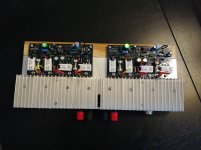
1) replaced all the cabling for signal ground and dirty ground (these are 2 separated cables from the ground star to the PCB). Used thicker 18 AWG stranded wire.
2) replaced twisted pair cables for input (RCA socket => PCB) - I used thicker, stranded wires from the old SCSI computer cable, instead of thin, solid core used before.
3) ground wires are soldered to the posts on the PCB (no spades anymore)
All of this did require full re-assembly of the amp/chassis.
Run tests on the oscilloscope - now I don't see any crossover distortion
at any frequency - each channel separately, and wired together.
Also, no any kind of other distortion visible to naked eye, all waves look perfect.
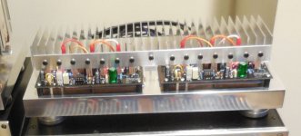
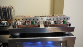
Idle current right now at 80mA. Transistors running definitely hotter than before. Copper spreaders were not getting any warmer before, now they are noticeably warmer.
The idle current trimmers are kind of sensitive, I should have resistor + trimmer in the PCB design. Let's see if idle current remains stable.
Now it's playing music, everything sounds great.
Photos 'before' (yellow wires) and 'after' (black wires).
Maxim, how did you know it's ground's fault?
Drivers are running now at 50 degrees C, still OK.
1) replaced all the cabling for signal ground and dirty ground (these are 2 separated cables from the ground star to the PCB). Used thicker 18 AWG stranded wire.
2) replaced twisted pair cables for input (RCA socket => PCB) - I used thicker, stranded wires from the old SCSI computer cable, instead of thin, solid core used before.
3) ground wires are soldered to the posts on the PCB (no spades anymore)
All of this did require full re-assembly of the amp/chassis.
Run tests on the oscilloscope - now I don't see any crossover distortion
at any frequency - each channel separately, and wired together.
Also, no any kind of other distortion visible to naked eye, all waves look perfect.
Idle current right now at 80mA. Transistors running definitely hotter than before. Copper spreaders were not getting any warmer before, now they are noticeably warmer.
The idle current trimmers are kind of sensitive, I should have resistor + trimmer in the PCB design. Let's see if idle current remains stable.
Now it's playing music, everything sounds great.
Photos 'before' (yellow wires) and 'after' (black wires).
Maxim, how did you know it's ground's fault?
Drivers are running now at 50 degrees C, still OK.
Attachments
Last edited:
Steve, solution with LEDs for drivers looks very interesting/unique.
Sim looks great.
I can't try it on this amp - it's already all soldered on PCBs, and it's working fine now,
but I still have PCBs, and a lot of N-Channel Fets left 🙂
There is nothing I can do with them, except for quasi amps 🙂
Will see if I can use these PCBs with LEDs, or need new ones..
Sim looks great.
I can't try it on this amp - it's already all soldered on PCBs, and it's working fine now,
but I still have PCBs, and a lot of N-Channel Fets left 🙂
There is nothing I can do with them, except for quasi amps 🙂
Will see if I can use these PCBs with LEDs, or need new ones..
Last edited:
Just the first thing I thought ofMaxim, how did you know it's ground's fault?
Let's wait for Egra's build, and see what he thinks.
His version employs just 1 pair of output devices, this will be much easier.
HexFet multi-pairs like to oscillate (at least from my experience), if not matched correctly (or even if matched..).
And matching them is pain in the neck. Seems easy, but every time I'm measuring them at higher currents, I'm getting different numbers, to the point of being totally irrelevant..
Say, I'm measuring a batch of 20 fets, writing down numbers. Tomorrow will repeat whole exercise, and will be getting different numbers..
Last edited:
Regarding post/schematic #994:
1) caps C9/C12 - I've seen some cases when this caps are connected to rails (not to GND), or (as in case for C12) to the collectors of drivers.
Maxim consistently uses GND. I used to use rails.
What is better/correct? Sim seems to work equally fine with both..
2) Speed-up cap between bases of output devices - not needed anymore? I guess not for Fets..
3) When testing/siming with square waves, adjustments of C5/R1 were usually needed - increasing either value was usually in order. Does it matter what do we increase? Capacitance vs Resistance?
Last edited:
The C5/R1 chain (post 994) is a common pre-correction. Correction for the advance of the output signal . Additionally, the DC voltage level at the output of the operational amplifier is changed /forced transfer of the operational amplifier VC to mode a .In addition to reducing opamp distortion, this circuit provides a higher rate of increase in the output voltage of the amplifier . As for choosing to support cascode, I want to hear other opinions first.Although both options are quite feasible .
Last edited:
- Home
- Amplifiers
- Solid State
- Unusual amp from 1987