Well.The disadvantage is one.Worse use of power supply voltage
And I'm still trying to do a phase-linear amplifier one.More precisely, the printed circuit board. .I just don't know whether to do it or not.
And I'm still trying to do a phase-linear amplifier one.More precisely, the printed circuit board. .I just don't know whether to do it or not.
Last edited:
This I don't care. I have PSUs from 20V to 80 V rails.
Doesn't doesn't have to be efficient.
What the heck - I have class A amps that can heat my room in winter...
Doesn't doesn't have to be efficient.
What the heck - I have class A amps that can heat my room in winter...
It is good in winter at-30g Celsius.It's been a long time, really.This I don't care. I have PSUs from 20V to 80 V rails.
Doesn't doesn't have to be efficient.
What the heck - I have class A amps that can heat my room in winter...
ок .Thank you for the article
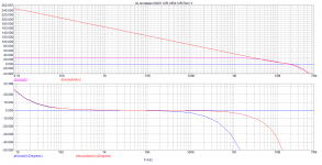
linear phase 10herz-100kHz. lower graph
linear phase 10herz-100kHz. lower graph
Attachments
Last edited:
Up to 20 kHz, the phases are almost identical . The prototype in the hardware is functional .But while there are problems with the PCB.
I just don't know if this phase makes sense or not
I just don't know if this phase makes sense or not
Last edited:
I think PCB will be fine. I made 3 PCBs for 4 amps - it's a similar topology.
And my PCBs are not perfect. They don't have ground plane like yours.
And they all worked just fine. No hum, no un-explainable oscillations.
As long as ground(s) is routed correctly, power and signal ground separately, they will work ok...
And my PCBs are not perfect. They don't have ground plane like yours.
And they all worked just fine. No hum, no un-explainable oscillations.
As long as ground(s) is routed correctly, power and signal ground separately, they will work ok...
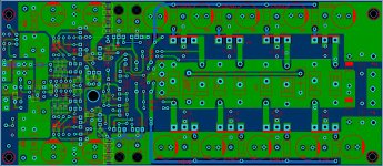
Very nice board. But if I was a transistor, I wouldn't care if layout or tracks are symmetrical or not 🙂
This is purely for esthetic reasons
====================================
Очень красивая печатная плата. Но если бы я был транзистором, мне было бы все равно, симметричны ли компоновка или дорожки 🙂 Это чисто из эстетических соображений
This is purely for esthetic reasons
====================================
Очень красивая печатная плата. Но если бы я был транзистором, мне было бы все равно, симметричны ли компоновка или дорожки 🙂 Это чисто из эстетических соображений
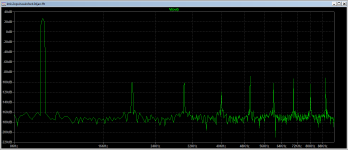
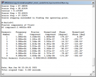
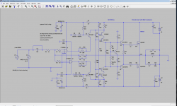
I quickly put together 2 op-amps + Hawksford cascode VAS.
I guess the overall results are similar to the latest/best non-symmetrical schematic, but SR is at least 100V/us.
Plots for 1kHz and 10kHz (at full power). Very nice square waves too. Very stable and tolerant.
I guess the overall results are similar to the latest/best non-symmetrical schematic, but SR is at least 100V/us.
Plots for 1kHz and 10kHz (at full power). Very nice square waves too. Very stable and tolerant.
Attachments
-
 lmk.2ops.hawksford.04jan.10khz.fft.png24.5 KB · Views: 690
 -
 lmk.2ops.hawksford.04jan.10khz.thd.png25.4 KB · Views: 660
 -
 lmk.2ops.hawksford.04jan.1khz.fft.png25.7 KB · Views: 712
 -
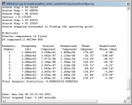 lmk.2ops.hawksford.04jan.1khz.thd.png25.3 KB · Views: 775
 -
 lmk.2ops.hawksford.04jan.png71.7 KB · Views: 713
 -
lmk.2ops.hawksford.04jan.asc11.9 KB · Views: 603
Last edited:
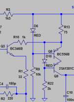
This is very simple schematic.
I bet you can slap your voltage shifter/buffer, a coil or two and make it much better 🙂
======================
Это очень простая схема. Бьюсь об заклад, вы можете использовать свой переключатель напряжения / буфер, катушку или две и сделать это намного лучше 🙂
I bet you can slap your voltage shifter/buffer, a coil or two and make it much better 🙂
======================
Это очень простая схема. Бьюсь об заклад, вы можете использовать свой переключатель напряжения / буфер, катушку или две и сделать это намного лучше 🙂
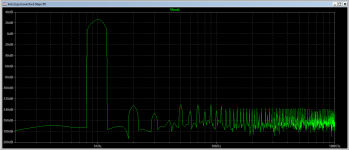
-120db 1000hz/There are many distortions. But the rate of increase is higher/ Everywhere you have to look for a compromise.I don't like the throttle.they are capricious.
Last edited:
Yeah, your last non-symmetrical was flatter (Thd at 1kHz), at or below 150dB.
That's because more complex voltage shifter (4 transistors).
Here there is only 1.
Tomorrow will try to combine both of them. But it seems little bit over complicated...
Transistor count is growing...
That's because more complex voltage shifter (4 transistors).
Here there is only 1.
Tomorrow will try to combine both of them. But it seems little bit over complicated...
Transistor count is growing...
Last edited:
A compromise. You reduce distortion, the rate of voltage rise decreases. How to find the middle
But from what I see, Hawksford cascode VAS improves everything,
so it's worth using, regardless of the input and middle stage implementation.
==============
Но из того, что я вижу, каскадный VAS Хоксфорда все улучшает, так что его стоит использовать, независимо от реализации ввода и среднего этапа.
so it's worth using, regardless of the input and middle stage implementation.
==============
Но из того, что я вижу, каскадный VAS Хоксфорда все улучшает, так что его стоит использовать, независимо от реализации ввода и среднего этапа.
- Home
- Amplifiers
- Solid State
- Unusual amp from 1987