How much thd is the CFP loaded with constant current source alone? I don’t know 30ppb is good or not without comparison.Remember, the original circuit achieves ~30ppb THD with 10Vpp ouput, and is stable: it has been tried and tested.
Is this buffer some variant of LT1010?
Like this.
The circuit relies mainly on bootstrapping to minimize the distorsions.
It does work, but bootstrapping brings difficult stability issues.
Note that it is not one of my "official" projects, I simply asked for advice to solve difficult issues.
My official projects are carefully tested and vetted to be easily reproducible by anyone; this is not one of them.
People are free to use it and modify it according to their taste, but I give no guarantee regarding the stability and performance.
I'll post some pics of my build later
By that you mean rated for voltage ?For your application, don't forget to add robust input protection components
and thanks very much for above reply !
No, I mean protection diodes, at least D6 and maybe D7:

The actual OP transistors are TO5, like the ones used in HP instruments: something like 2N3866 or 5109 or 2N588-something, a fast PNP.
Here is how the thing looks:


Edit: IIRC the PNP output transistor could be a 2N5160; there must be a 2N588 something too, but I am too lazy to go up in my lab and look into my components drawers. Later
The actual OP transistors are TO5, like the ones used in HP instruments: something like 2N3866 or 5109 or 2N588-something, a fast PNP.
Here is how the thing looks:
Edit: IIRC the PNP output transistor could be a 2N5160; there must be a 2N588 something too, but I am too lazy to go up in my lab and look into my components drawers. Later
Last edited:

Thanks for the pics. Too bad there's no click response for admiration/being impressed.
Unwise to go with the BJT numbers in the schematic?
Are those shields around the TO-5's?
Unwise to go with the BJT numbers in the schematic?
Are those shields around the TO-5's?
The BJT's in the sim have a lower power dissipation, which can be a problem in the real world, where the power can be much higher on a short-circuit: the device is essentially a lab accessory, meaning it has to take any abuse thrown at it
Sorry, I know it's your day off today but. . . .
All those apparently unused pads filled with solder. Are you using them with leads underneath to make rails? I've noticed the same look on some of your other perf builds.
All those apparently unused pads filled with solder. Are you using them with leads underneath to make rails? I've noticed the same look on some of your other perf builds.
I used parallel 3 of TO-92 BJT in my simulation.They are just small cooling clips
Yes, for some of them at leastSorry, I know it's your day off today but. . . .
All those apparently unused pads filled with solder. Are you using them with leads underneath to make rails? I've noticed the same look on some of your other perf builds.
In fact, for audio in front of a sound card, the bandwidth is vast overkill. I needed it because of the heterodyne configuration of the analyzer, but for general purpose audio, there is no need for it, and the circuit can probably be made more stable more easily with more reasonable specs, without affecting the low frequency linearityI changed to dual power supply 15VDC and modify a little bit.
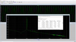
This simple buffer can be achieved very low distortion and wide band. Even at 1 MHz the distortion still low enough.
Thank you Elvee.
As I mentioned in the post #81, it is just a discrete implementation of the buffer chip LT1010. Here is a simulation of a simplified LT1010.
I recommend just using opamp in the position like below instead of building a discrete circuit. Thus, you don't need to figure out the stability.

I recommend just using opamp in the position like below instead of building a discrete circuit. Thus, you don't need to figure out the stability.
Last edited:
@jxdking The load should 1K Ohm, not 100 Ohm for buffer. It is not for headphone amplifier. The signal frequency should use 20 kHz, the theoretical of highest frequency in audio. In my simulation, even with 100 kHz signal, 5 V peak, the THD still better using discrete. The bootstrapping should be compensated and the current source as load for the emitter follower also need compensation. The capacitor at base of emitter follower also important. The discrete is ALWAYS have possibility to have better performance than the integrated. And it make the discrete interesting.
Regarding the stability, There are 2 things that you need to watch out for.The bootstrapping should be compensated and the current source as load for the emitter follower also need compensation. The capacitor at base of emitter follower also important.
1. The stability of the negative feedback that makes the current going through the CFP constant.
2. The stability of the unit buffer. If you load the emitter follower(CFP in this case) with small capacitor(it could be some internal capacitance from the transistor in CCS), also the input is inductive due to long leads, it will oscillate. Like the situation as my other post.
Thread 'How (Not) to Make An Oscillator with Emitter Follower'
https://www.diyaudio.com/community/...e-an-oscillator-with-emitter-follower.421436/
Only getting to this a few minutes at a time so no soldered progress yet but adding D6 and D7 to the asc file made for a change in the output waveform. I don't really understand what it means but It's interesting and thought it might be worth mentioning.
Attachments
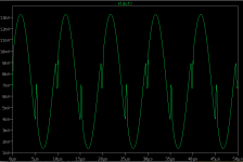
You have forgotten to add n=6 to the diode D3:

A random thought: if you intend to use this with an oscilloscope probe, you will have to add a resistor a little larger than 1 megohm (the bias resistor is bootstrapped and appears much larger than 220K) and increase the input capacitor to 15 or 20pF, to fall within the compensation range of the probe
A random thought: if you intend to use this with an oscilloscope probe, you will have to add a resistor a little larger than 1 megohm (the bias resistor is bootstrapped and appears much larger than 220K) and increase the input capacitor to 15 or 20pF, to fall within the compensation range of the probe
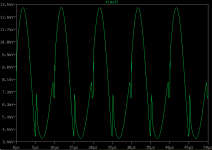
Thanks for keeping watch. It's the first time I know of this way of adding series components and a reminder to me of the danger of not seeing what one doesn't already recognize. n=6 added and output trace is now beautiful in spice.
And just to be sure I understand : Your "random thought" advice above is referring to R3 and C7 ?
Many thanks !
And just to be sure I understand : Your "random thought" advice above is referring to R3 and C7 ?
Many thanks !
Looking around for small value tantalum caps I don't find any at Digikey or Mouser. Would other film types work for C4 , C7 & C8 ?
C7, yes but the additional ~1.1 megohm should be in // with the input, upstream of C1. R3 being bootstrapped, the effect would be negligible.And just to be sure I understand : Your "random thought" advice above is referring to R3 and C7 ?
The capacitors you mention are in the pF range, meaning your only option is ceramic
- Home
- Amplifiers
- Solid State
- Unstable buffer