Now your tube is completely cut off, drawing no current. If the grid (pin 2) is 10.2 volts (about right) the cathode (pins 1,3 and 9) needs to be about 12 volts for proper conduction. What voltage does any of these pins read with the tube installed and the pot turned from one end to the other.?
Pins 1, 3 and 9 are all connected together, yet you report different voltage readings. I'm not sure what the voltage reading should be with no tube installed, but I'll measure my board as soon as I can get it working.
An accidental overdose of electricity (over 600 volts) has left my board with several dead parts. R7 got so hot that it unsoldered itself and fell out of the board. I have changed several parts and it still doesn't work right. It is clear that a 6.8K resistor for R7 was fine when I was running a few mA through each driver tube and using a B+ of 450 volts or less. It is NOT fine when cranking over 30 watts from each channel on about 500 volts with 10 mA flowing through each driver tube. I now have a 1.2K 2 watt resistor in the board for R7, but there are still dead parts in here somewhere as nothing works right.
The big Toroid.com transformer that I first tried got me 545 volts even when I was drawing 300 mA of current. I swapped in an Antek which had lousy regulation but got me about 485 volts when drawing 300+ mA. Unfortunately the B+ was well over 600 volts when all tubes were cold on power up. That blew up the screen regulator because I had a 500 volt fet installed. There is still something else dead as all voltage readings are whacky.
My current favorite needs 1.2 volts to hit 20 watts where it makes 1.14% THD. It eases gently into clipping near 25 watts where it makes 2.67% THD, and clips pretty hard at 30 watts where it makes 6.05% THD.
Those are impressive numbers! Sorry that your board went “pop” with that overdose. Good luck with getting it to run smoothly again.
Regarding R7 - do you see any problem with my plan of replacing it with a 16H, 40 ma, ~600 Ohm choke to make available as much HV as possible from my regulated supply off Q1.
Last edited:
The different results between pins 1, 3, and 9 is just me playing with the pot between each measurement. If I leave it alone they measure all the same.
Regarding R7 - do you see any problem with my plan of replacing it with a 16H, 40 ma, ~600 Ohm choke to make available as much HV as possible from my regulated supply off Q1.
Oops, I meant “as much HV as possible from my B+” (not regulated supply off Q1).
Last edited:
I am usually OK with blowing stuff up in the name of science. In this case I saw the 26HU5's show a bit of plate glow when idle on nearly 500 volts at about 120 mA, so I did the obvious, I installed the fattest 26LW6's that I have. They were cold, so the B+ went somewhere beyond the range of the 600 volt scale on my cheap DVM which made some dead parts.Those are impressive numbers! Sorry that your board went “pop” with that overdose. Good luck with getting it to run smoothly again.
Regarding R7 - do you see any problem with my plan of replacing it with a 16H, 40 ma, ~600 Ohm choke to make available as much HV as possible from my regulated supply off Q1.
I had seen the voltage drop across the zener diode when turning the pot on the input tubes while using a 10 mA CCS for the plate load, so I had swapped the 150K R8 for the first big resistor I found which was a 39K 3 watt part. It got hot, but not too hot. It now looks like the zener got hot too since it is also unsoldered on one end. It is however still alive.
I see no reason why you couldn't use a choke in place of R7, but I have not actually tried it. I have a box full of mystery chokes nearby, so I may try one later after things are working better. I now have power, but lots of distortion. Perhaps resoldering the zener will fix it. Don't know yet since I took the board out and brought it to my "building stuff" workbench for a general clean up. There is more light here, and this is where I noticed the unsoldered diode. I have made a mess out of the soldering changing parts from the top over the last few days.
The impressive measured numbers can be obtained by applying a small amount of feedback from the output tube to the driver tube. This is accomplished by soldering a large value 2 or 3 watt resistor to the junction of R114 and R115 and running a wire from the other end of this resistor to the junction of R105, R106 and R107 (pin 2 of the driver tube). This gives up some gain for increased power output and lower distortion. I have not yet listened to the amp wired like this so I don't know how it will sound. I do know that I was getting over 30 watts from each channel at under 3% THD when I decided to install bigger tubes and try again. Do not try this mod until everything else is working correctly. I have used a 510K resistor with a 6JD6 tube but it didn't have quite enough gain. I now have a 1 meg 2 watt resistor in there and I have seen good results with every driver tube I tried except some Japanese 6KY6's.
I'll get back to this in an hour or two. I have some outdoor work to do.
I'll get back to this in an hour or two. I have some outdoor work to do.
Attachments


I took some measurements with the driver tubes in
Bad channel
1, 3 and 9 - 13.1v
2 - 10.2V
7 - 340v
8 - 99v
Good channel
1, 3 and 9 - 9.5v
2 - 8.5V
7 - 225v
8 - 98v
On the bad channel pins 1, 3, and 9 do respond to the pot. Initially the reading was 33v, 13.1v is the lowest I could adjust it down to.
Bad channel
1, 3 and 9 - 13.1v
2 - 10.2V
7 - 340v
8 - 99v
Good channel
1, 3 and 9 - 9.5v
2 - 8.5V
7 - 225v
8 - 98v
On the bad channel pins 1, 3, and 9 do respond to the pot. Initially the reading was 33v, 13.1v is the lowest I could adjust it down to.
This all points to the mosfet. is the correct part installed correctly?
Try sticking a small resistor, say 560 ohms to 1K from pin 1 to ground and see what the tube voltages do. If the plate voltage comes down, the fet, pot, R102, or R103 are not working correctly. Does the voltage on the wiper of the pot vary when you turn it?
Try sticking a small resistor, say 560 ohms to 1K from pin 1 to ground and see what the tube voltages do. If the plate voltage comes down, the fet, pot, R102, or R103 are not working correctly. Does the voltage on the wiper of the pot vary when you turn it?
Well that was annoying. Replaced the mosfet again and now everything seems good. This is the 3rd mosfet I have tried while troubleshooting this issue. The mosfet I removed tests as a mosfet on a cheap mega tester I have but something was wrong. Bad part, bad soldering? Good thing I purchased a number of these from Digikey. Thanks for your help. Now I can get back to playing with this amp and some of your tweaks.
The measurements you are posting above using the feedback mod, was that using a 3K or 1.5K OPT load? Is that also with r113/213 at 15k?
The measurements you are posting above using the feedback mod, was that using a 3K or 1.5K OPT load? Is that also with r113/213 at 15k?
The OPT is wired for a 1500 ohm load. I recently got a pair of Toroidy 600 ohm OPT's. Once I get life flowing from my board I may try them as 1200 ohm OPT's just to see if I can blow the board up again. R113 and R213 are now 15K.Well that was annoying. Replaced the mosfet again and now everything seems good. This is the 3rd mosfet I have tried while troubleshooting this issue. The mosfet I removed tests as a mosfet on a cheap mega tester I have but something was wrong. Bad part, bad soldering? Good thing I purchased a number of these from Digikey. Thanks for your help. Now I can get back to playing with this amp and some of your tweaks.
The measurements you are posting above using the feedback mod, was that using a 3K or 1.5K OPT load? Is that also with r113/213 at 15k?
It looks like I blew my last "blow proof" screen regulator mosfet. They are $10 each and nobody has any in stock. Some digging into the data sheet reveals that the 500 volt fet I chose is only good for 500 volts in short pulses of 10 mS or less. The expensive POS (piece of silicon) is only good for 400 volts continuously. I'm putting one of the cheap parts in, so I won't be too upset when I blow it.
I always get poor THD measurements when I hook up the OPT for a 1.5K load. Usually somewhere around double to triple the THD and less power compared to 3K.
I have tried I think all the changes discussed in the last few posts one at a time and measured the results. My baseline setup prior to this gave 0.55% THD at 1W and 5% at 17-18W. I am not using a B+ regulator right now so it measures 465V at R1 and 421V at C2. Output tube bias set at 100mA, tubes 12GN7A/26HU5
First change was adding in the CCS. I set it at 10mA and soldered it in place of R108/208. I found dialing in the plate voltage unstable like this so soldered in a 1M resistor across the R108/208 below the CCS, This made things stable. I also reduced R7 to 3.4K and R8 to 75K ohms as well as put the 56V zener back in at D4. This setup gave 0.44% THD at 1W and about the same 5% at 17-18W. Driver plate voltage is set at 250V
Next I reduced R113/213 to 15K. Gain increased and so did distortion, THD was about 0.81% at 1W. Not a good change on it's own.
Last I added in the feedback mod. To do this I had to put 5 200K ohm 1/2W resistors in series since that is all I had to get me there. Much less gain now. THD at 1 W is 0.3% and I get 20W at 3% THD. My DAC at full output drives it to 13V but the THD spectra starts to look a little ugly.
So improvements but not as good as George's results yet. I then hooked it up to my garage speakers. It sounds good, I don't think these changes spoiled the good sound of the UNSET. Listening over the weekend will be a better test though when I can crank it up and see how it sounds at a proper level of output.
Had a chance to do some listening over the weekend and am happy with the sound of the UNSET setup like this. It still has the same overall sound and punch as before with perhaps a little more crispness to the music. THD has moved a little lower with 0.28% at 1W, 1.14% at 10W, and 2.9% at 20W, THD spectra is 2H dominant to 20W. However I see the output screen voltage start to drop at around 20W. This is also at 100% output of my DAC so I can get more using a preamp with some gain but it starts to get real ugly as output surpasses 20W and I see the screen voltage drop at this point. Perhaps I will try to reduce the 2K resistor and see if this helps.
I also tried installing a 270uF 500V electrolytic cap in at C2 and removing the 2 100uF motor run caps. I was hoping this would save some space when I eventually put this all in a chassis. I did not like the result. The amp sounded off, a bit muffled, just not as clean. I ended up removing it and wired back in the motor run caps and just leaving C2 unpopulated. Good sound was back.
One thing I know is I am not pushing the tubes as hard. I have bumped it up a bit over spec at 36W total dissipation using 100mA of bias but know if I pushed the tubes harder distortion would be lower. I think this is one reaon my THD is not as good as what George measured. Also my results are all with the OPT wired for a 3K load. I just can't get good results with them wired for 1.5K. This I don't understand since George is getting such good results at 1.5K. What could be the difference?
Friday, I took the board out of my test setup to clean up the mess of poorly soldered parts that had been tacked on, removed, swapped a few times, or just burnt due to contact with a soldering iron in my shaky hands. I also replaced anything that looked like it had eaten too much power. Remember, my board has seen over 600 volts.
Saturday, I began to reassemble and test everything and search for a suitable power transformer so that I may look toward building a complete UNSET amp. All measurements have been done with bench power supplies up to this point. Maximum power tends to be lower once an unregulated supply is used. At this time, I discovered two inconsistencies in my setup that may make some of my previous measurements suspect. When I got the rebuilt board up and running one channel made more power than the other. I also noted that the heat sink on one channel was hotter than the other. Investigation revealed that one channel was wired for 1500 ohms and the other was wired for 3000 ohms. One of the cheap meters that I had been using to set the bias current was bad due to an overdose of electricity. This led to the hot channel running a lot more current than I thought.
I did find results similar to yours. With the OPT's wired for 3000 ohms I got good results up to almost 20 watts with bias currents in the 100 to 110 mA range. This would limit the B+ to under 450 volts to get a semi - sane tube dissipation level with even the biggest 'LW6 tubes I have. Operation on 1500 ohms requires a bunch more current, and a corresponding lower B+ voltage to control tube dissipation. Any of the 360-0-360 volt transformers that I tried delivered a B+ voltage in the 480 to 500 volt range. I saw power levels over 30 WPC with the Antek which delivered the lowest B+ voltage. Unfortunately even the Antek produced some plate glow in a dark room when run at enough current for the THD to level off. I decided to explore lower voltages at higher currents and a 1500 ohm load. Here I needed to be in the under 400 volts range.
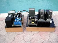
By Saturday night all was working properly. After about 5 different tries I found a suitable power transformer that would deliver 396 volts to the OPT's at idle, and 375 to 385 volts at 30 WPC depending on where I set the idle current. In order to get good THD at 30 watts into 1500 ohms, I need about 150 mA of tube current. This is too much for the power transformer I have, but for now it's the best I can do with parts at hand. I have been using an SMPS to power the heaters of the output tubes for all tests so far. The transformer I found has a 6.3 volt winding with 8 amps of current, so it is powering all the heaters and some fat 6LW6's are in the board. Note that there are two different size bottles for 'LW6 tubes, and several different plate structures. I picked a pair with the fat bottles and the biggest plates. Yes, that little choke is a bad joke, but all I could find on short notice. I do have a bigger one somewhere.
Bench testing revealed that I could easily get 30+ watts at under 5% THD with both channels driven, but it took about 150 to 160 mA to get there. At this level there was no plate glow in a dark room. Sherri and the neighbor next door would both be away all afternoon Sunday, so I could make all the noise I wanted, so I dragged out my trusty Yamaha NS-10M Studio monitors, attached a volume pot and some input jacks, plugged in a DVD player, and set up for some serious listening tests.
Why Yamaha NS-10's? I bought them in the early 90's, before Tubelab even existed, and I was involved with early 16 bit digital audio recording with a PC. My daughter played keyboards and drums and was the drum captain of the local high school marching band. We had a room full of musical weaponry, including some of my guitars and DIY guitar amps. There was usually several kids making some kind of music in that room whenever they weren't in school. The Yamahas do percussion right, and I have used them for testing and critical listening on every Tubelab amp ever made. They are rather inefficient at 87dB though.
Sadly, the critical listening tests did not occur yesterday. Our power went out as we were leaving for church and did not come back on until 8 PM last night. I did get about 45 minutes of "loud" time before Sherri came home. I learned that 150 mA of idle current makes the heat sinks on the cathode fets too hot to touch, so a fan was placed near the board. It ran fine like this, but I kept reducing the current during listening to see where the reduction became audible. Around 130 mA there are noticeable artifacts on transient sounds as the amp is pushed near clipping. This becomes visible on the scope below about 120 mA. I set the current to 135 mA and turned the fan back on. There should be some more listening time on Tuseday night.
Saturday, I began to reassemble and test everything and search for a suitable power transformer so that I may look toward building a complete UNSET amp. All measurements have been done with bench power supplies up to this point. Maximum power tends to be lower once an unregulated supply is used. At this time, I discovered two inconsistencies in my setup that may make some of my previous measurements suspect. When I got the rebuilt board up and running one channel made more power than the other. I also noted that the heat sink on one channel was hotter than the other. Investigation revealed that one channel was wired for 1500 ohms and the other was wired for 3000 ohms. One of the cheap meters that I had been using to set the bias current was bad due to an overdose of electricity. This led to the hot channel running a lot more current than I thought.
I did find results similar to yours. With the OPT's wired for 3000 ohms I got good results up to almost 20 watts with bias currents in the 100 to 110 mA range. This would limit the B+ to under 450 volts to get a semi - sane tube dissipation level with even the biggest 'LW6 tubes I have. Operation on 1500 ohms requires a bunch more current, and a corresponding lower B+ voltage to control tube dissipation. Any of the 360-0-360 volt transformers that I tried delivered a B+ voltage in the 480 to 500 volt range. I saw power levels over 30 WPC with the Antek which delivered the lowest B+ voltage. Unfortunately even the Antek produced some plate glow in a dark room when run at enough current for the THD to level off. I decided to explore lower voltages at higher currents and a 1500 ohm load. Here I needed to be in the under 400 volts range.
By Saturday night all was working properly. After about 5 different tries I found a suitable power transformer that would deliver 396 volts to the OPT's at idle, and 375 to 385 volts at 30 WPC depending on where I set the idle current. In order to get good THD at 30 watts into 1500 ohms, I need about 150 mA of tube current. This is too much for the power transformer I have, but for now it's the best I can do with parts at hand. I have been using an SMPS to power the heaters of the output tubes for all tests so far. The transformer I found has a 6.3 volt winding with 8 amps of current, so it is powering all the heaters and some fat 6LW6's are in the board. Note that there are two different size bottles for 'LW6 tubes, and several different plate structures. I picked a pair with the fat bottles and the biggest plates. Yes, that little choke is a bad joke, but all I could find on short notice. I do have a bigger one somewhere.
Bench testing revealed that I could easily get 30+ watts at under 5% THD with both channels driven, but it took about 150 to 160 mA to get there. At this level there was no plate glow in a dark room. Sherri and the neighbor next door would both be away all afternoon Sunday, so I could make all the noise I wanted, so I dragged out my trusty Yamaha NS-10M Studio monitors, attached a volume pot and some input jacks, plugged in a DVD player, and set up for some serious listening tests.
Why Yamaha NS-10's? I bought them in the early 90's, before Tubelab even existed, and I was involved with early 16 bit digital audio recording with a PC. My daughter played keyboards and drums and was the drum captain of the local high school marching band. We had a room full of musical weaponry, including some of my guitars and DIY guitar amps. There was usually several kids making some kind of music in that room whenever they weren't in school. The Yamahas do percussion right, and I have used them for testing and critical listening on every Tubelab amp ever made. They are rather inefficient at 87dB though.
Sadly, the critical listening tests did not occur yesterday. Our power went out as we were leaving for church and did not come back on until 8 PM last night. I did get about 45 minutes of "loud" time before Sherri came home. I learned that 150 mA of idle current makes the heat sinks on the cathode fets too hot to touch, so a fan was placed near the board. It ran fine like this, but I kept reducing the current during listening to see where the reduction became audible. Around 130 mA there are noticeable artifacts on transient sounds as the amp is pushed near clipping. This becomes visible on the scope below about 120 mA. I set the current to 135 mA and turned the fan back on. There should be some more listening time on Tuseday night.
Attachments

spigg, I following your experiments with interest while being distracted by building a Tubelab SPP with 6P15P-EV output tubes. Just to be clear: Your weekend setup included the feedback mod, the CCS at 10 ma in place of R108/208 (bypassed with 1 meg), B+=420V at C2 and 26hu5 screens regulated at ~180V.
20 watt at <3% distortion is excellent performance for a 26HU5 dissipating under 40 watts! It would be nice to get distortion lower than 1.3% at 10 watts output. I don’t know where to look for it, and I probably couldn’t hear it anyway.
Your finding with the motor run caps are interesting! Have you tried both “lytics“ and motor caps?
Edit: George your post arrived while I was typing mine. Your experimentations and your accounts of it are very interesting. Too bad your power went out when you had the opportunity to do some serious “loud” listening.
Thank you for your further tweeks and experimentation. Personally I would be happy with a good 20 watts and an outstanding first 10 watts.
Last edited:
I look for a pristine "first watt" then try to keep the next 19 reasonable and orderly.Personally I would be happy with a good 20 watts and an outstanding first 10 watts.
For anything other than some of today's over compressed "dance" music the peak to average ratio is well over 10 dB, often 20 to 30 dB. This means that an amp that is just touching 20 watts on peaks is averaging 200 mW to 2 watts (20 to 10dB peak to average). This is often called the crest factor, but there are differences between how the two are measured.
In the DSP controlled RF amplifier world we often accepted the bit errors that would occur on a random worst case peak as long as there weren't enough of them to cause enough distortion to fail an out of bandwidth energy test. We employed digital peak reduction in the DSP to intentionally squash the dynamic range to allow for a more efficient RF amplifier. Much of today's music is intentionally squashed to make it sound louder, since the average SPL is what the ears "measure."
This kind of testing often correlate with music reproduction as the same errors occur. A random clipped peak on a drum or bass transient will often go unnoticed. It's the non musical IMD products that these brief overloads create when that overload causes mixing with the other music present at the time that gets heard. Even then, if such an event occurs once every second or two in a passage of music, and that passage is loud, it may not get heard due to masking. When the music is made by human musicians the chances of several instruments hitting peak output at exactly the same time is not great. When that music is made in a computer and all of the "digital instruments" are time aligned, the frequency of all the peaks lining up is often much greater. Fortunately most of the DAW's used in modern music making now allow for messing with the timing of each instrument to better mimic a human. I was cranking some 80's techno music at the edge of clipping last night and this peak alignment was evident even on the scope screen. The UNSET however did not make too much of a mess out of it though. An amp with a lot of GNFB often does, especially when driving a speaker.
Yes, that was my weekend setup. I might try to increase the CCS to 15mA and see if it does any better. I am close to under 1% at 10W 🙂...Just to be clear: Your weekend setup included the feedback mod, the CCS at 10 ma in place of R108/208 (bypassed with 1 meg), B+=420V at C2 and 26hu5 screens regulated at ~180V.
20 watt at <3% distortion is excellent performance for a 26HU5 dissipating under 40 watts! It would be nice to get distortion lower than 1.3% at 10 watts output. I don’t know where to look for it, and I probably couldn’t hear it anyway.
Your finding with the motor run caps are interesting! Have you tried both “lytics“ and motor caps?...
I did try both electrolytic and film caps in combination after the choke. My favorite has been with just the motor run caps or in combination with a small electrolytic cap at C2.
What I have seen with the 3K OPT is inline with what George is saying. They want at least 95mA bias but ideally in the 100-110mA + range to perform best.
One other note according to the spec sheet my DAC puts out a max of 1.5V rms and that will drive the UNSET to ~20W.
Tested the CCS at 15mA with the 12GN7A driver tubes. Worse in all measures, they definitely liked 10mA better. I also discovered my laptop power supply is now starting to put some measurable distortion into the system, tests will be on battery power from now on.
Something else I tried was to drop the 2K resistor on the screen supply down to 1.8K to see if a small adjustment would make a difference. It does, at just over 20W the screen voltage dips by about 1-1.5V with the 1.8K resistor where as before with a 2K resistor it was dropping by around 5-8V. George you mentioned in the build notes the 2K resistor is there to protect the fet. I have about 420V of B+ after the choke on my setup (Antek AS-3T350). How much would I be pushing it if I was to drop this down to say 1.5K?
Last test of the night, tried bringing the driver tube screen voltage up to 100V. This also required dropping R8 to 42K to keep the voltage stable. A little improvement, 1W THD at 0.27% and 10W at 1.02%. So what if I gave it just a bit more bias? Brought the current up to 105mA for 38W of total dissipation. So is that ~36W on the plate? Not too much over spec. So here you go Francois G, 0.24% THD at 1W and 0.88% at 10W. Max output is still ~20W but perhaps we could see more with a change in the Q1 fet resistor and more than 1.5V RMS from the source. THD spectra looks good as well. No chance to listen tonight but perhaps a little time tomorrow.
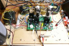
I used to have a Windows XP PC set up for FFT measurements with Win Audio MLS using a 15 year old M-Audio Audiophile 24/192 card. It worked great and had flat loop back response out to 90 KHz. That PC died several years ago and I recently built a slightly newer Windows 7, 4th gen Intel core i5 machine running REW. All alone sitting on the workbench it had a usable loopback response with nearly 90 db of dynamic range. That PC is now sitting between the HP audio analyzer and the Yamaha speaker in the picture above. Unfortunately just turning the PC on raises the noise floor into the 1% THD range without even connecting it to the amp under test. My next move is to get the PC further away from the test station and possibly move to a USB sound box like the Focusrite Solo.Tested the CCS at 15mA with the 12GN7A driver tubes. Worse in all measures, they definitely liked 10mA better. I also discovered my laptop power supply is now starting to put some measurable distortion into the system, tests will be on battery power from now on.
I have run several different driver tubes through my board with the CCS circuit. So far most of the TV IF amp tubes like about 7 mA, the TV video amp tubes like the 12GN7 like 10 mA and the 6HB6 can go a bit higher, but I find no improvement over 10 mA.
The 2 K resistor value was determined back in the time that I was running B+ voltages in the 500 to 600 volt range. It allows for lower dissipation in the mosfet but also keeps you from melting a screen grid when banging the amp into hard clipping. It does this by forcing the screen voltage to drop when the screen current goes into the red glow region. The value of this resistor is determined by the B+ voltage being used at the time. I have reduced the value of this resistor several times as I have moved lower and lower in the B+ voltage range. I had a 1.5K 5 watt resistor in my board when I last blew it up. That resistor was open (dead) due to a wayward application of 600 volts. In retrospect, the dead 50 cent part probably saved my 26LW6's. Now that I'm working with under 400 volts of B+ I have moved to a pair of 500 ohm 5 watt parts in series (1 K total) since the 6LW6's that are in the amp now seem to eat a bit more screen current than the 26HU5's. The idea would be to pick a resistor value that causes the screen voltage to drop at a power level beyond where you would normally run the amp, maybe the point of 5% or so THD with both channels driven. This causes a gentle clipping instead of a chopped top on the sine wave, which is generally less sonically intrusive.Something else I tried was to drop the 2K resistor on the screen supply down to 1.8K to see if a small adjustment would make a difference. It does, at just over 20W the screen voltage dips by about 1-1.5V with the 1.8K resistor where as before with a 2K resistor it was dropping by around 5-8V. George you mentioned in the build notes the 2K resistor is there to protect the fet. I have about 420V of B+ after the choke on my setup (Antek AS-3T350). How much would I be pushing it if I was to drop this down to say 1.5K?
I had an older Antek AN-4T360 wired into my amp. It gave me about 480 B+ under full load which made over 30 watts per channel, but resulted in too much tube dissipation. I switched to a Hammond 272JX 300-0-300 @ 250 mA transformer which gives me about 400 volts at idle and 385 volts at 25 watts with both channels driven to 4% THD. I left the amp running at this power level for about 20 minutes and it got quite hot. I then removed the drive and let it idle for about an hour (worst case heat on any class A amp) with a fan blowing across the heat sinks. The Hammond got too hot to touch, but the amp survived.
I am now setting things up to try two older Antek AN-1T150's wired in series to see if I can get my B+ down a few more volts. I still have a few more surplus transformers in my box of iron to try.
I took two Antek AN-1T150's, wired all 4 primaries, and all 4 6.3 volt secondaries in parallel and all 4 HV secondaries in series to create a transformer with lots of 6.3 volt power and a 600 volt CT winding which made 647 VAC with no load. I connected this mess to the UNSET board. The B+ was over 400 volts with no output tubes installed, 398 volts with them installed but biased to cutoff. The B+ drops to 355 volts at 125 mA per output tube, 352 volts at 135 mA per output tube, and 349 volts at 150 mA per output tube.
I rolled through a bunch of 6LW'6's testing for plate glow in a darkened room. Oddly some of the tubes with the biggest fins attached to the plate showed color at the lowest dissipation level. Some of the later vintage tubes with no extra fins ate the most power before getting red faced. I selected a pair of Westinghouse branded GE's that took nearly 60 watts to exhibit glow. I put these into the amp and set the current to 135 mA (42 watts). The amp had about 4 millivolts of 60 Hz residual (no surprise with the messy wiring) on it's output which was enough to make for erroneous THD readings at low power levels unless the 400 Hz HPF was engaged, so it was used for all testing.
THD was 0.17% at 1 watt, 0.54% at 5 watts, 0.97% at 10 watts, and 1.83% at 20 Watts on the worst of the two channels. Clipping appeared at about 22 watts and THD hit 5% at about 25 watts. The other channel was slightly better, but not much. Raising the idle current to 150 mA (46.5 watts) brought small improvements in THD below 10 watts and bought maybe an extra watt of power before clipping. I used 135 mA for all testing and listening.
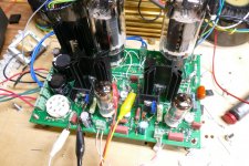
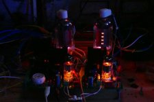
The amp was powered up continuously for over 4 hours. After dark I took the obligatory shot in the dark picture, and had the current turned up to 150 mA for about 10 minutes at idle (no music) which is worst case for any class A amp dissipation wise. There is a dull glow on the sides of the plates that face each other. The glow faded when I cranked up some loud music at full tilt with occasional clipping seen on the scope. After the first hour I pointed a small fan at the heat sinks as the one on the right had reached 80 degrees C on my cheap IR thermometer. With some airflow it dropped to under 60C. The Anteks were pretty hot, but not too hot to touch.
I threw everything at this amp from mellow to metal with a detour through some uber compressed 80's techno. The bass was solid and I didn't need to crank up the idle current to reduce the boom like I do on a SSE running KT88's in UL. In this regard, the UNSET beats the SSE hands down. It would take a side by side comparison to chose an overall winner between the UNSET and my last high powered SE amp (the UNSET wins in the bass department despite the small OPT), which is an 845 being driven by a TSE board for about 30 WPC on 1050 volts. That amp still sits on a shelf and has not seen power for over 10 years.
I rolled through a bunch of 6LW'6's testing for plate glow in a darkened room. Oddly some of the tubes with the biggest fins attached to the plate showed color at the lowest dissipation level. Some of the later vintage tubes with no extra fins ate the most power before getting red faced. I selected a pair of Westinghouse branded GE's that took nearly 60 watts to exhibit glow. I put these into the amp and set the current to 135 mA (42 watts). The amp had about 4 millivolts of 60 Hz residual (no surprise with the messy wiring) on it's output which was enough to make for erroneous THD readings at low power levels unless the 400 Hz HPF was engaged, so it was used for all testing.
THD was 0.17% at 1 watt, 0.54% at 5 watts, 0.97% at 10 watts, and 1.83% at 20 Watts on the worst of the two channels. Clipping appeared at about 22 watts and THD hit 5% at about 25 watts. The other channel was slightly better, but not much. Raising the idle current to 150 mA (46.5 watts) brought small improvements in THD below 10 watts and bought maybe an extra watt of power before clipping. I used 135 mA for all testing and listening.
The amp was powered up continuously for over 4 hours. After dark I took the obligatory shot in the dark picture, and had the current turned up to 150 mA for about 10 minutes at idle (no music) which is worst case for any class A amp dissipation wise. There is a dull glow on the sides of the plates that face each other. The glow faded when I cranked up some loud music at full tilt with occasional clipping seen on the scope. After the first hour I pointed a small fan at the heat sinks as the one on the right had reached 80 degrees C on my cheap IR thermometer. With some airflow it dropped to under 60C. The Anteks were pretty hot, but not too hot to touch.
I threw everything at this amp from mellow to metal with a detour through some uber compressed 80's techno. The bass was solid and I didn't need to crank up the idle current to reduce the boom like I do on a SSE running KT88's in UL. In this regard, the UNSET beats the SSE hands down. It would take a side by side comparison to chose an overall winner between the UNSET and my last high powered SE amp (the UNSET wins in the bass department despite the small OPT), which is an 845 being driven by a TSE board for about 30 WPC on 1050 volts. That amp still sits on a shelf and has not seen power for over 10 years.
Attachments

My measurements are close to yours George. With my setup I am seeing 0.22% 1W, 0.54% 5W, 0.88% 10W and 1.9% 18W. Output will just touch 20W at 2.9% THD then everything falls apart quickly. I did try to lower the screen supply resistor to 1.5K and while the screen voltage didn't drop more than a few volts at 20W+ the distortion was still climbing rapidly so at this point I don't think I am really gaining anything with the lower value. I switched back to the 2K value for the above measurements. I am running 105mA bias and this puts the tubes at 38W.
- Home
- More Vendors...
- Tubelab
- UNSET Beta Board Build