https://elektrotanya.com/luxman_cl34_sch.pdf/download.htmlReproduce luxman cl34 heater supply and heater wiring It's totaly silent and it has a small secret that will help you every single time you meet weird constraints! By the way...you can go opposite way too, lowering the fillament potential below ground!
That is a nice heater supply. Interesting line schematic too, SE to LTP, PP to second gain stage, no need for Ck and provides SE output.
You could take it one step further, +/- supply from seperate transformer: https://www.diyaudio.com/community/...a-thoroughly-modern-tube-phono-preamp.163570/
HMN is single supply for anode-cathode potential.Only the heaters are +-.
Having built a measurably more performant mm phono preamp based on d3a than hmn or luxman and a clone to cl34 I dare to say that luxman performance is simply put stellar.You can get simillar performance to cl34 , but you cannot make a better preamp based on tubes in the audio range.Luxman knew their stuf.And ecc83/ef86 tube types give the optimum SNR/transconductance ratio.You can get better measurable SNR with ecc83, d3a or other high GM tubes, but for 32...100 times more anode current and more complication on the supply part while ef86, ecc83 work under 1mA doing just about the right job.ecc83 also has better VKF specs than usual higher transconductance tubes.You can lift the fillament potential or go under the ground up or down -50v with no negative consequence. If you can't hear their noise it doesn't matter what noise you measure.
Unfortunately the price for good ecc83 has gone through the roof as D3A price did as well so people can't make a difference today...
Yes and I think that's okay - the potential difference is effective to reduce heater cathode coupling regardless of absolute polarity.HMN is single supply for anode-cathode potential.Only the heaters are +-.
As I see it, the clever part is use of +/- supply to increase common mode rejection and the seperate heater transformer is an added bonus.
Hi, which type did you find to be the good ECC83, and was this only with the cl34, or elsewhere as well?.Unfortunately the price for good ecc83 has gone through the roof as D3A price did as well so people can't make a difference today...
Also, if I can ask about the EF86, same same. Thank you.
- sorry if off topic but seems helpful/good value.
Last edited:
With the input shorted from de mu-follower and 2k load at the output was the noisefloor -81db. So sorry for my previous -116db. And 0.025% THD + N With 1khz test signal at 2.83V out.This is an amazingly good noise floor. . Can you show the actual measurement and the conditions under which they were made please?
Cheers
ian
Thanks for the update. That looks more like the kind of figure I would expect. By the way, what level corresponds to 0dB? Would that be 2V rms?
Cheers
ian
Cheers
ian
OK, in which case in future it would be better to quote it as 0dBu.0db refers to 0.775 Vrms.
Cheers
Ian
Not really. dBFS is not an absolute measure. What is means in absolute terms depends on the interface used to convert the analogue input to digital. But I am sure you knew that.More correctly as -18dBFS.
I am sure I had you googling 🙂
Cheers
Ian
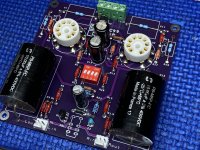
I received the SMPS and powered it up, unloaded.
There is a jumper that selects between 200V/260V and also a trimpot for fine adjustment. With the jumper set for 260V, the trimpot adjustment range was 250V-290V. But, the filament voltage also varied, 7.5V when HV was 290V. Take these numbers with a grain of salt, when a load is connected I anticipate slightly different voltages.
The attached video shows the filament voltage coming up first followed by a several second delay before the HV slowly ramps up to its set voltage point.
Well, apparently I don’t know how to post a video on this forum

The heater supply is unregulated and follows the HV supply as you have seen. At 260/265V the heatersupply gives about 6.3V.

Hello Vunce, looking good.
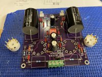
But one remark, it is better to put the tubesockets on the bottomside of the PCB.
Otherwise the pinlayout is wrong.

But one remark, it is better to put the tubesockets on the bottomside of the PCB.
Otherwise the pinlayout is wrong.
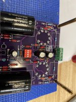
Hi Vunce, hope you have a good desoldering iron - as shown in your photo, you have pin 1 of the tube socket soldered to pin 9 land on the board - yes you need to have the tube socket on the back of the pcb. This enables the pcb to be slung under the lid with the tubes protruding above the cover, which is better for cooling and also allows for easy tube rolling. Otherwise, your build is first class.
Yeah, realized that after they were installed. Before soldering, I checked pin9 to ground and thought all was good, but labeling for pin1/pin9 is mirrored from backside of pcb 🙄.
Time to break out the Hakko FR301….
Time to break out the Hakko FR301….
- Home
- Amplifiers
- Tubes / Valves
- Universal tube preamp PCB, ECC99/6N6P/ECC88/ECC85/6922/6DJ8 etc. MU follower or SRPP