I've never seen any documentation on the MKII other than the advertisement.
Wondering - what output transistors do your MKII amps have?
Wondering - what output transistors do your MKII amps have?
Pete,
The output transistors are Motorola MJ802 and MJ4502. BTW, Both transistors have another number under them MJ802 then 7326 under it and MJ4502 and 152 under it, any idea what those numbers are?
Thanks,
Bobby
The output transistors are Motorola MJ802 and MJ4502. BTW, Both transistors have another number under them MJ802 then 7326 under it and MJ4502 and 152 under it, any idea what those numbers are?
Thanks,
Bobby
Those are the right parts, I have a MKII here that was probably rebuilt and has the wrong outputs. Those are date or lot codes. 7326 is probably 26th week of 1973.
I received them from my father in law who had used them as his first amps (he has since moved on to bigger and better amps). He still swears by them though. In all the years of use by him and sitting packed up in the garage and then a year or two of use by me, they do sound pretty decent and I've read all the posts about burning tigers but the only thing that gets warm on them are the power transformers 🙂
What are better spec transistors for Q5 and Q6? I don't recall what I have in my B's. Since this thread won't die, I mean keeps getting better, we should come up with a list of replacement parts to keep these amps alive.
I'll start:
Bigger PS caps. I'm using 10,000uF 75v Sprages and haven't had a PS failure since the upgrade. They do not fit in the original chassis. If someone found similar caps (Mouser source?) that will fit in the chassis, please post.
I've plugged in a pair of 22,000 @ 50V Phillips computer grade capacitors into each of my Tiger .01s, along with higher current stealthy rectifiers... They just barely fit, and I wish I could snag some more from that local surplus parts store.
The original caps died relatively quickly; the new caps will probably last longer than me! I experimented with some rail bypass caps from the PCB to the star ground, but I think it's running just fine without that usual design precaution.
--Damon
Last edited:
A first, I would remove capacitor in series with feedback resistor. Second, added Zobel network for dominant pole compensation. And third, replaced that bogus thermal stabilization network by better one, that does not blow up output transistors during adjustments, due to noises in trimpot that cause high current spikes.
Nearly each student in our campus in 1970'th designed something similar learning by hard way. 😉
Nearly each student in our campus in 1970'th designed something similar learning by hard way. 😉
It doesn't blow up during bias adjustments... it blows up when you unplug the input, or overdrive it, etc...
where do you want to add that zobel network for compensation?
_-_-bear
where do you want to add that zobel network for compensation?
_-_-bear
but when you rotate the trimpot contact is not perfect... and due to noises it's resistance jumps up... that may cause too high bias current spikes... that blow up output transistors... I've seen that many times...It doesn't blow up during bias adjustments... it blows up when you unplug the input, or overdrive it, etc...
where do you want to add that zobel network for compensation?
Either from VAS collector to ground, or to it's base... as usual... and remove that cap from feedback... that most probably come there from tube amp designs... that for measurement sake used it to fight ringing in output transformers... otherwise it's appearance is unexplainable...
I just found this thread. I built multiple copies of most of the Tiger amps starting with the original SWTPC kits and then cloning the boards myself and using whatever parts I could find. Yes, some went bang on take-off, and some lived long lives as guitar amps. The original Universal Tiger design appeared in Popular Electronics twice that I know of. The first time was probably in 1970 since I started one in high school and I graduated in 1970. It appeared in the 1973 Popular Electronics Handbook, I have the copy in front of me.
I know of 4 basic designs, but I seem to remember a 5th. As stated there were a few variations of the bigger versions. The little one was appropriately named the Lil Tiger. 22 watts from all plastic transistors all mounted to the PC board. I made a few of these, starting in high school. The next size was the Plastic Tiger I think it made about 35 watts and I made dozens of these. I used them in guitar amps, home stereos, and car amps.
In the mid 70's I had a shagged out van with "octasonic" sound. 8 Plastic Tiger amps and 1 Universal Tiger running off a home made switcher. It was fed from my Craig Pioneer Quadraphoinc 8 track deck! The van shook with bass.
I made a few Universal Tigers but never build the Tigersaurus. I thought there was another size between the Plastic and Universal Tigers. I built the SWPTC 6800 computer too.
So why am I saying all this. Ever see the TV show hoarders? Some people never throw anything away. You know some day I might want to finish all of these......
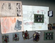
Anybody want this stuff.....PM me, sent free for the cost of postage. The small boards are Plastic Tigers, the large boards are Universal Tigers. Some have never seen power. These are all home made boards from the early 70's, not great quality, but usable. I can't find the magazine with the Plastic Tiger article, but I have the 1973 experimenters handbook. There might be some more Plastic Tiger boards hidden in the closet. I built another car stereo amp in college (mid 90's).
I know of 4 basic designs, but I seem to remember a 5th. As stated there were a few variations of the bigger versions. The little one was appropriately named the Lil Tiger. 22 watts from all plastic transistors all mounted to the PC board. I made a few of these, starting in high school. The next size was the Plastic Tiger I think it made about 35 watts and I made dozens of these. I used them in guitar amps, home stereos, and car amps.
In the mid 70's I had a shagged out van with "octasonic" sound. 8 Plastic Tiger amps and 1 Universal Tiger running off a home made switcher. It was fed from my Craig Pioneer Quadraphoinc 8 track deck! The van shook with bass.
I made a few Universal Tigers but never build the Tigersaurus. I thought there was another size between the Plastic and Universal Tigers. I built the SWPTC 6800 computer too.
So why am I saying all this. Ever see the TV show hoarders? Some people never throw anything away. You know some day I might want to finish all of these......
Anybody want this stuff.....PM me, sent free for the cost of postage. The small boards are Plastic Tigers, the large boards are Universal Tigers. Some have never seen power. These are all home made boards from the early 70's, not great quality, but usable. I can't find the magazine with the Plastic Tiger article, but I have the 1973 experimenters handbook. There might be some more Plastic Tiger boards hidden in the closet. I built another car stereo amp in college (mid 90's).
Attachments
Do you have any MJ802/4502s from that time by any chance?
Yes the UT was in the October 1970 issue of PE:
http://www.swtpc.com/mholley/PopularElectronics/Oct1970/PE_Oct1970.htm
You might get a kick out of this:
http://www.swtpc.com/mholley/PopularElectronics/Popular_Electronics.htm
Yes the UT was in the October 1970 issue of PE:
http://www.swtpc.com/mholley/PopularElectronics/Oct1970/PE_Oct1970.htm
You might get a kick out of this:
http://www.swtpc.com/mholley/PopularElectronics/Popular_Electronics.htm
Last edited:
Do you have any MJ802/4502s from that time by any chance?
There is one pair of 1973 vintage Motorolas on the little "L" bracket in the picture. Cases are dented but probably OK. There may be another pair in my thumper amp if I can find it.
Update:
I found the "Master Blaster" amp that I built in the 90's. It has been gutted and contains no MJ802's or 4502's. It contains 2 of the 4 original plastic tiger boards all built with substitute parts, probably working boards, and one fried SMPS.
Last edited:
Measured Reverse BE Breakdown Voltage (Vebo)
Measured 2 pairs of 40409/10s for Vebo and they ranged from 8 to 10V
Also measured 2 pairs of current Fairchild BD139/140-16 parts and they ranged from 8 to 13V
Most parts are rated for 4 to 6 Vebo and this measurement was to confirm that the junctions will breakdown with 14 to 18V across them as seen under harsh clipping conditions in the UT:
http://www.diyaudio.com/forums/soli...-tiger-improved-simulation-2.html#post2585028
Last edited:
Measured Vceo for several parts
I also measured the collector to emitter breakdown voltage for several parts:
1973 pair of MJ802/4502, 92V and 94V very close to the 90V spec. these are
from George at tubelab.com and I don't know their history.
Pulled another pair from a very beat up stereo UT that tested good and they
were both over 100V the limit of the bench power supply that I had handy.
Measured 4 old stock 40409/10s and they all passed the 100V limit of the test.
Measured 4 new Fairchild BD139/140-16 which were also over the 100V limit of the test,
interesting that they are only rated for 80V.
I used a 100K current limiting resistor that limits the current to 1mA worst case for zero volts across the device and much less for higher voltages. Most data sheet specs use higher currents as the limit.
Transistor Breakdown meter circuit here < http://www.seekic.com/forum/22_circuit_diagram/20997_TRANSISTOR_BREAKDOWN_TESTER.html > Dont know if its any good.
I made a few Universal Tigers but never build the Tigersaurus.
I built 8 tigersaurus amps. They all worked great, but the heatsinking wasn't too good for long term power. Essentially, it was just heat capacity with little air movement..half the sinks were inside the case and designed to prevent airflow. Rebuilt them all using 5 inch fans and a tunnel sink arrangement.
Cheers, John
Do you have any MJ802/4502s from that time by any chance?
Hi Pete
I happen to have some MJ802/4502. Original Motorola (yr 1994). New-unused. 5 pairs in total.
If you like to have them, let me know.
these are from George at tubelab.com and I don't know their history.
I don't either. I can guess that they were samples from the in house MOT SPS office back in 74 or so. We got free samples by the boxload then. About the only thing they wouldn't give us was SRAM for our SWPTC based computers. The transistors were probably used in a UT or Plastic Tiger and removed. We used those aluminum L brackets to bolt the TO-3 devices to some big heatsinks since we got them from line scrap. They have been in the box on the shelf since I moved into this house in 1978. There were a few of us making audio amps in the 70's. I wound up with all the leftovers when the Tiger building eventually died off. We built a lot more Plastic Tigers (many with TO-3 outputs) than UT's. Most were for car amps and the UT's needed more volts than we could make then, and shredded the car speakers of the 70's.
Our "audio club" turned into the Bob Carver fan club and most everybody just bought Carver or Phase Linear equipment and quit building stuff. I still have a Carver M-400 and a Phase Linear 4000 stuffed in the back of the closet too. Neither have seen power in 25 years or so.
Universal Tiger MKII Schematic
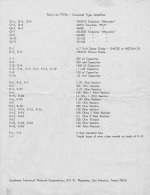
George also sent the Universal Tiger MKII schematic which is the version with protection transistors and a few other minor changes:
C8 reduced to 100 pF
C10 reduced to .01 uF
R28 added 1K in series with the base of Q1
R27 added 4.7K in tail of diff pair
R21 bias pot increased from 50 to 250 ohms
R22 added 150 ohms across R21
Protection is SS1122/23 transistors:
C to base of outputs
E to rail
B through 150 ohms to Emitter of outputs
15K from B to output collector
Schematic and parts list are attached.
Attachments

I have the docs on that version as well, but does anybody have an image of the board layout? SWTPCo seemed to keep that one under wraps, as the docs only show the board outline and the extra two connections for the protection. If anybody could even photograph the back of an assembled one, that would be useful.
- Home
- Amplifiers
- Solid State
- Universal Tiger