NS10 Lineamp
In the meanwhile we get the Gerber’s here is how the NS10 will look like. I had to eliminate all lettering there to be able to post it on a PDF file.
Input to the left is the regulated supply at 24VDC
Upper right is signal input from source
And middle right is Signal Out from the lineamp.
C10 (decoupling) is optional when supplying from Tooleregs on short leads.
Different options on input caps are shown.
C11 (feedback cap) is not part of the original circuit as far as we know but has been left there since we think it could be nice to have as option.
Rest of the circuit is as faithful to the original as far as it was reconstructed in one of the NS10 threads with input from Nelson itself.
🙂
Attachments
are the resistor values from E96 series? Why?
Why is R5 1k0? ~25mA through the LED. R5 dissipates ~ 620mW. It would need to be a 1W or preferably 2W if 1k0 is important. nb. R2 is 10k and that CCS works with 2mA through the LED.
Why is R5 1k0? ~25mA through the LED. R5 dissipates ~ 620mW. It would need to be a 1W or preferably 2W if 1k0 is important. nb. R2 is 10k and that CCS works with 2mA through the LED.
Thanks for your time. I was needing regulators for the D1 I/V stage for the Buffalo DAC that should arrive soon. I want to use four regs on the Buffalo, 5V and 3.3V(X3). I also need to power the D1 at +/-30VDC so these will be perfect there. I just wish it had enough current to power my Aikido 24V headamps. I love that I get a bunch a raw linear PS PCBs as well so that I can use them for LED lighting in my new house and with the thermoelectric/liquid cooling for my system.
A couple of quick questions...
1. I know that it has been tried at 5V, but will it be stable at 3V3?
2. What is the maximum current it can supply at 25.2V?
3. Would there be any way of implementing them in a HTPC for all but the fans?
David
A couple of quick questions...
1. I know that it has been tried at 5V, but will it be stable at 3V3?
2. What is the maximum current it can supply at 25.2V?
3. Would there be any way of implementing them in a HTPC for all but the fans?
David
Apropos D1, take a look here🙂
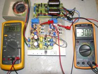
I just build the compact version and it is powering a D1 while adjusting and watching. The compact version works, so I guess that is good news.
R5 that Andrew mention does get hot . It is approx 70 Deg C. I am using 0.6 watt resistors.
🙂
I just build the compact version and it is powering a D1 while adjusting and watching. The compact version works, so I guess that is good news.
R5 that Andrew mention does get hot . It is approx 70 Deg C. I am using 0.6 watt resistors.
🙂
Attachments

R5's value is, as you pointed out, rather low. It is kind of a holdover from lower voltage versions of the project, and just something that I never thought to change, so this one is on me. Thanks for bringing it up. There is no reason for it to be this value, and honestly, since we are trying to make this more a universal project, it would be kind of beneficial to replace R5 with a simple CCS, as changes in the input voltage change the current through this resistor, which changes the current the big input CCS is sourcing. Something like a simple JFET, depletion mode MOSFET, or a CRD (if you must).AndrewT said:are the resistor values from E96 series? Why?
Why is R5 1k0? ~25mA through the LED. R5 dissipates ~ 620mW. It would need to be a 1W or preferably 2W if 1k0 is important. nb. R2 is 10k and that CCS works with 2mA through the LED.
1. I have posted 5v and 3.3v versions of the shunt reg, using a LED for the voltage reference. Just for you though, here it is again: http://img.photobucket.com/albums/v323/cetoole/PCB Layouts/discreteshuntreg33v.pngkhundude said:Thanks for your time. I was needing regulators for the D1 I/V stage for the Buffalo DAC that should arrive soon. I want to use four regs on the Buffalo, 5V and 3.3V(X3). I also need to power the D1 at +/-30VDC so these will be perfect there. I just wish it had enough current to power my Aikido 24V headamps. I love that I get a bunch a raw linear PS PCBs as well so that I can use them for LED lighting in my new house and with the thermoelectric/liquid cooling for my system.
A couple of quick questions...
1. I know that it has been tried at 5V, but will it be stable at 3V3?
2. What is the maximum current it can supply at 25.2V?
3. Would there be any way of implementing them in a HTPC for all but the fans?
David
2. How much heatsinking can you provide? Honestly, I dunno what the limits are, I havnt simulated or built above 100mA.
3. Only if you are a madman, and I mean that in the best possible way. The current draw in a HTPC is so high as to make linear supplies of any sort impractical, and a shunt regulator would be much worse, especially since a computer isnt a constant load. You thought Papa used big heatsinks to keep his stuff cool? Now, if you wanted, you could selectively power items, such as the soundcard, from a separate supply.
Wow Steen, looks great, though ideally, you would want about double that output capacitance. It will work fine where it is, but a bit better with a bit more. We are basically trying to tame the inductive spike in the output, though 4u7 gets most of it.
cetoole said:
R5's value is, as you pointed out, rather low.
Wow Steen, looks great, though ideally, you would want about double that output capacitance. It will work fine where it is, but a bit better with a bit more. We are basically trying to tame the inductive spike in the output, though 4u7 gets most of it.
Thanks, I sort of promised to build the compact today, to confirm if it is working, so I just used what I had in the drawer....
Would it be a good idea to double the resistance of R5 on the boards that I did build? It would be easy enough to solder in a bigger resistor. A simple Jfet CCS is probably a good bet for the final solution, or maybe a J5XX CCS. I will give it a try, as soon as there is a suggestion.
🙂
Manu said:
Nice baby ..
🙂
You still recognize the boards ? 😀
They worked right away, "no problemo" as they say in Mexico😉
🙂
Probably wouldnt be a bad idea, and if your input voltage is 36v, 10k would be appropriate for R5, or if you have a JFET or CRD around 2-3mA, you could just use that. You will also need to adjust R6 downwards a bit to keep the CCS current the same.steenoe said:
Thanks, I sort of promised to build the compact today, to confirm if it is working, so I just used what I had in the drawer....
Would it be a good idea to double the resistance of R5 on the boards that I did build? It would be easy enough to solder in a bigger resistor. A simple Jfet CCS is probably a good bet for the final solution, or maybe a J5XX CCS. I will give it a try, as soon as there is a suggestion.
🙂
Awesome build though. I have great respect for anyone who DIYs their own PCBs and builds something new.
Hey Steen, that was a quicky 😀 this show how easy is to work with those Compact versions. Very nice work to say the least, lots of hard work there which is greatly appreciated.
Did you connect the grd plane?
Did you connect the grd plane?
apassgear said:Hey Steen, that was a quicky 😀 this show how easy is to work with those Compact versions. Very nice work to say the least, lots of hard work there which is greatly appreciated.
Did you connect the grd plane?
Yep that was a quikky, indeed, and I did connect Manu's little J-gnd jumper.
I will check the J-fets I have tomorrow and see if I have some low Idss types. BTW, there is no varying voltage if the prereg is used, as here😉
BTW, I will also hook the I/V to my system tomorrow, to see if there are any issues. It's getting late here.
🙂
The varying voltage comes when you use it at 36v input, but someone else uses it at a different voltage.steenoe said:
Yep that was a quikky, indeed, and I did connect Manu's little J-gnd jumper.
I will check the J-fets I have tomorrow and see if I have some low Idss types. BTW, there is no varying voltage if the prereg is used, as here😉
BTW, I will also hook the I/V to my system tomorrow, to see if there are any issues. It's getting late here.
🙂
- Status
- Not open for further replies.
- Home
- Group Buys
- Universal shuntregulator, "Toolereg" NS-10 PCB-GB.