Sure,
But I am asking; how to connect grounds for seperated stereo boards with one psu?
I had bad experiences (huge ground loops) with that type of connections. But now I have to make another one and dont want to live these again..
But I am asking; how to connect grounds for seperated stereo boards with one psu?
I had bad experiences (huge ground loops) with that type of connections. But now I have to make another one and dont want to live these again..
I've tried a variety of stereo solutions and none are perfect for all situations.
The best of a bad bunch comes from:
dual rectifiers for each channel, separate Audio Grounds for each channel, separate Disconnecting Network from each Audio Ground to Safety Earth.
The best of a bad bunch comes from:
dual rectifiers for each channel, separate Audio Grounds for each channel, separate Disconnecting Network from each Audio Ground to Safety Earth.
So youre talking about the TOTAL seperation..
But, if you consider my situation; I have
- One transformer
- One regulated PSU board
- Two seperated amplifier boards...
Now, whats your advice for that?
I am planning,
One ground for each amplifier board (signal and power) (but input signal gnd is not connected) goes to the PSU boards common ground point.
One signal ground comes from the source and goes to this common ground point on the PSU board.
From the common ground point one stopper resistor (6R) goes to the main earth.
Do you think its fine?
this is dangerous.Dxvideo said:.................From the common ground point one stopper resistor (6R) goes to the main earth.
Do you think its fine?
You must not separate the Audio Ground from the Safety Earth with a resistor alone.
how about dual mono amplifier (each amplifier have one trafo and rectifier) + dual mono pre-amp (but only one regulator and trafos)
all the parts in one box.
total have 3 trafo and 3 rectifier.
can you help me, about the grounding schema?
all the parts in one box.
total have 3 trafo and 3 rectifier.
can you help me, about the grounding schema?
crt said:how about dual mono amplifier (each amplifier have one trafo and rectifier) + dual mono pre-amp (but only one regulator and trafos)
all the parts in one box.
total have 3 trafo and 3 rectifier.
so,are you going to use center trail transformer?
i just draw a grounding sch.
Attachments

digi01 said:
so,are you going to use center trail transformer?
i just draw a grounding sch.
Yes, i use CT transformer.
the picture you attached is for CT transformer right?
Many Thank's To you digi01

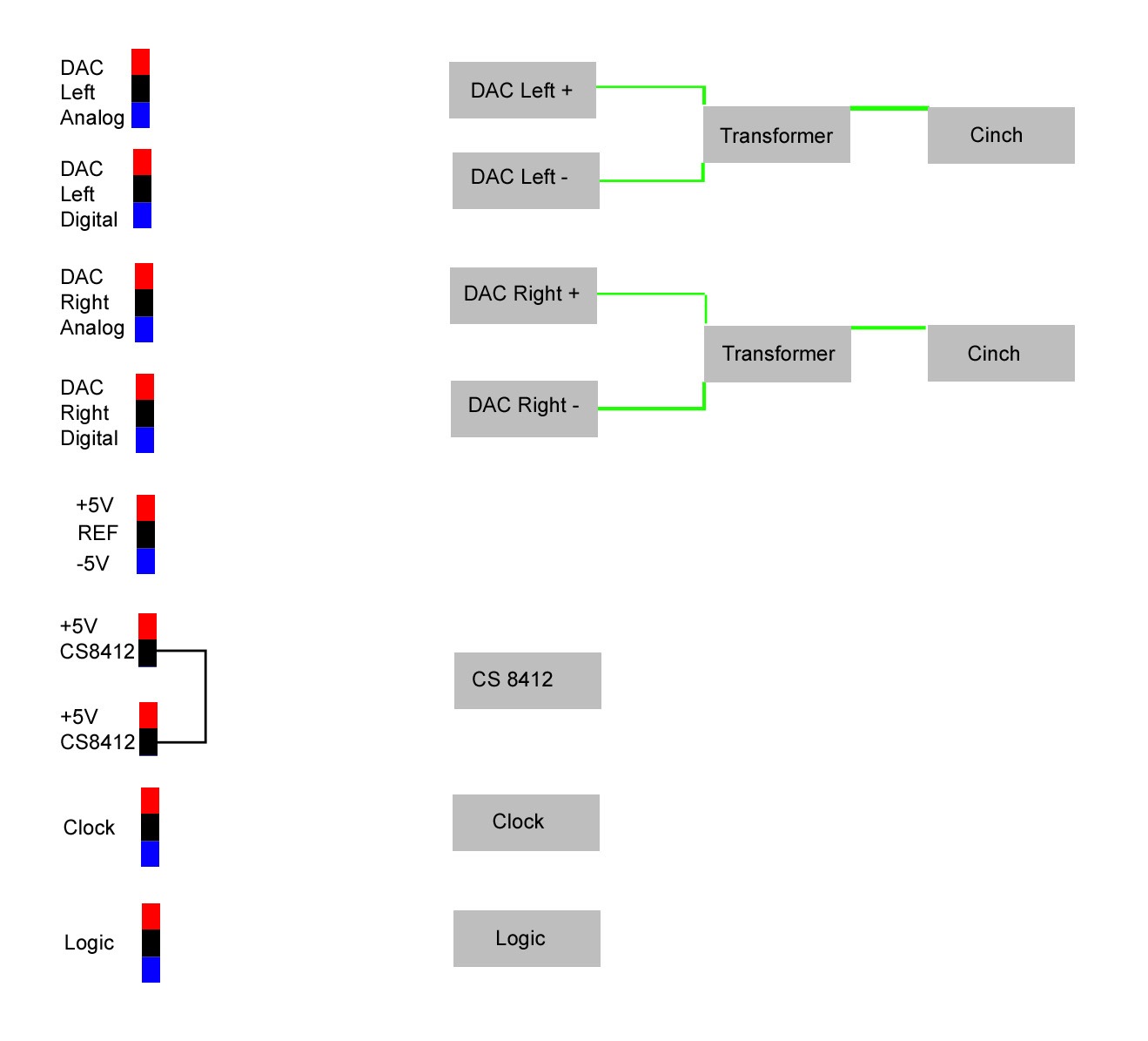
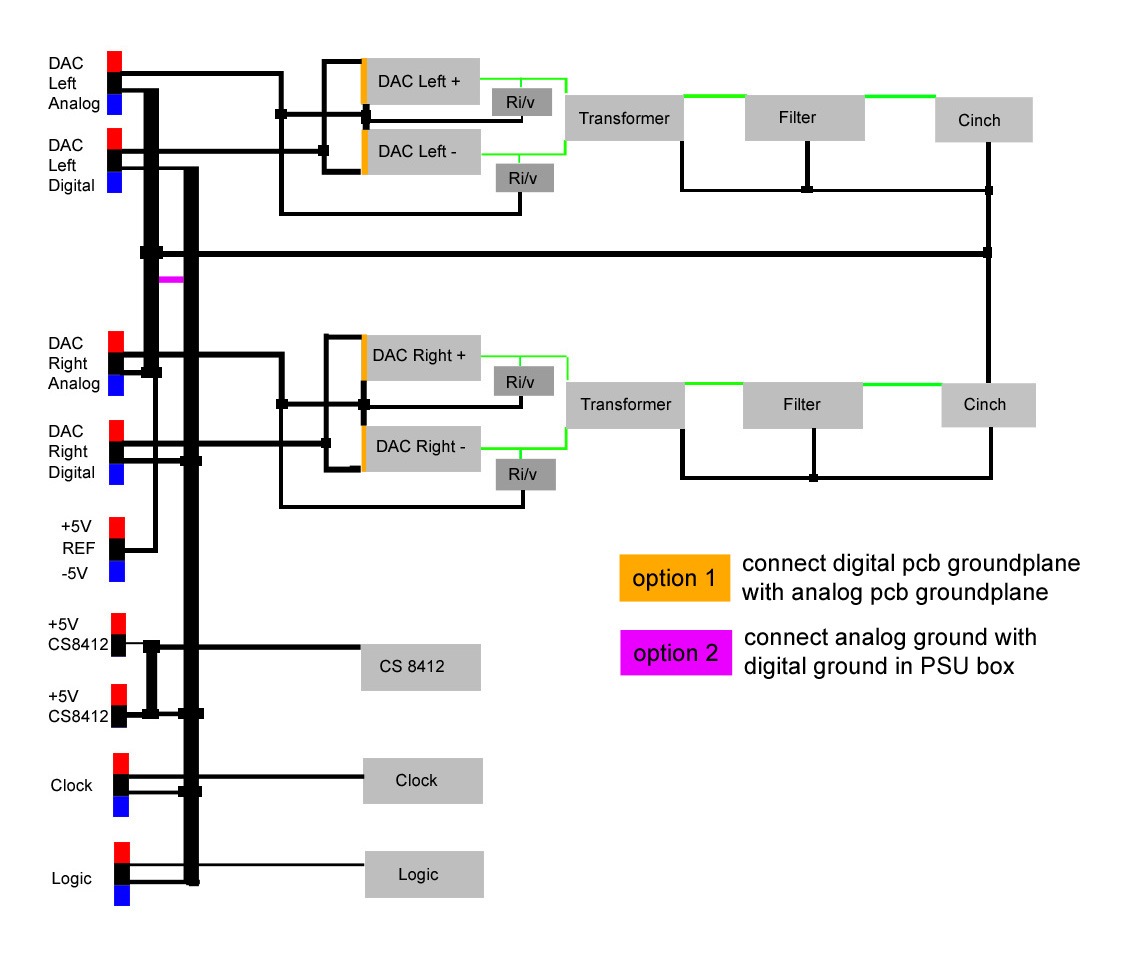
I am building the PSU for my DAC and I am not sure about the best grounding scheme.
All grounds in the PSU are separate except the two CS8412 grounds as indicated in the schematic.
Each grey DAC field needs one analog and one digital ground.
The datasheet suggests toconnect the grounds under the IC.
Each greay DAC field consists of 8 DAC chips and will have separate ground planes ( layers ) for analog and digital.
The Transformers and regulators shall be in an external box.
The REF is the voltage reference for each other regulator and needs a ground connectionto all of them.
Bernhard,
How many transformer are you going to use?
I will use at least two transformer.one for analog,the other for cs8412 and all the 5v digital circuit.I will not connect the analog ground and the digital ground directly.I will connect them with a 5 to 10mH inductance I think it is a good way.the ref ground as the digital ground too.
Zang
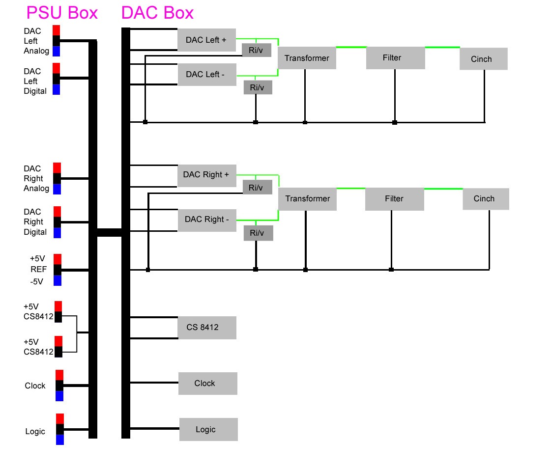
One possible solution with ground bars in both boxes and a fat cable, could that be regarded as "one" star ground ?
Maybe it would be better to return the analog and digital grounds separate to their respective power supplies...
Maybe it would be better to return the analog and digital grounds separate to their respective power supplies...
One possible solution with ground bars in both boxes and a fat cable, could that be regarded as "one" star ground ?
the solution is ok.you should setup the star gnd at the DAC box.
Maybe it would be better to return the analog and digital grounds separate to their respective power supplies...
no need to do these,it make things complicated.
simple is the best🙂
Zang
Thanks, the big question is wether the ground planes should be connected on the DAC board under each chip or not.
Best maybe is trial and error.
Also I did not care too much for good grounding on my prototype and there was no problem...
I will not post all possible schematics, here is one, I would prefer to connect analog and digital on the PSU:
Best maybe is trial and error.
Also I did not care too much for good grounding on my prototype and there was no problem...
I will not post all possible schematics, here is one, I would prefer to connect analog and digital on the PSU:
the big question is wether the ground planes should be connected on the DAC board under each chip or not.
i think so.the attached is my idea🙂
zang
Attachments
AndrewT said:Do we need a dedicated fourth conductor between the chassis?
Can the audio ground lead going to the disconnecting network do the duty of carrying fault current back to the PSU?
A bit late to the party, but going back to page 3 of the thread:
You could reduce the 4 wire "requirement" to a 3 wire system simply by moving the ground loop isolator (disconnecting network) to the amp box. If I end up needing a ground loop isolator, this is what I'll be doing.
Hi All,
I'm planning to build an amplifier, and I'm a bit confused about grounding.
For safety reasons I wouldn't like to cut safety and signal ground (or use a R-D-C loop breaker), but I know this would lead to ground loops and hum.
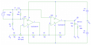
For this problem I have a little bit different approach. What if a special input stage is built to fight against ground loops? Not exactly a balanced input, but something that works similarly (I need only unbalanced inputs)
I've drawn the following schematic, simulated it, in theory it works fine. But in reality I'd use 1% resistors which would highly degrade the properties of the input stage, that's why there is a potentiomer in the circuit, to set the highest available common mode rejection.
What do you think about it? Would it work? How could I improve the schematics?
Thanks for your replies in advance!
I'm planning to build an amplifier, and I'm a bit confused about grounding.
For safety reasons I wouldn't like to cut safety and signal ground (or use a R-D-C loop breaker), but I know this would lead to ground loops and hum.
For this problem I have a little bit different approach. What if a special input stage is built to fight against ground loops? Not exactly a balanced input, but something that works similarly (I need only unbalanced inputs)
I've drawn the following schematic, simulated it, in theory it works fine. But in reality I'd use 1% resistors which would highly degrade the properties of the input stage, that's why there is a potentiomer in the circuit, to set the highest available common mode rejection.
What do you think about it? Would it work? How could I improve the schematics?
Thanks for your replies in advance!
Attachments
Originally posted by cpemma
Rod Elliott's article
He does point out "Be warned that this circuit (while safe) may not be legal where you live." so can anyone put particular countries to that?
I am also curious to know this 🙂
- Home
- Amplifiers
- Power Supplies
- understanding star grounding