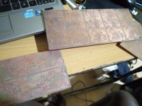
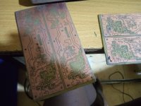
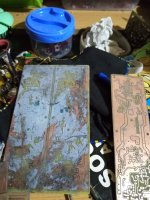
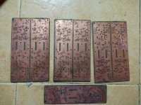
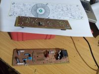
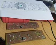
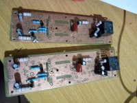
😕😕 and i have etched the pcb 😱😱
thanks manoj for the heads up , i will have to use jumper wires in the boards i have etched
Attachments
-
 IMG_20200515_193126_966.jpg449.9 KB · Views: 526
 -
 IMG_20200515_193131_738.jpg526.1 KB · Views: 511
 -
 IMG_20200515_200032_680.jpg834.5 KB · Views: 484
 -
 IMG_20200515_205655_909.jpg732 KB · Views: 462
 -
 IMG_20200515_205727_690.jpg833.9 KB · Views: 457
 -
 IMG_20200519_213710_093.jpg515 KB · Views: 195
 -
 IMG_20200519_213729 _832.jpg906.8 KB · Views: 172
 -
 IMG_20200519_213812_569.jpg591.5 KB · Views: 238
Last edited:
thank you but i mean eagle library you used to design this schematic and pcb
altium in convertion need that
you have to have the eagle software version 9 and higher
here you go sir .
have fun 😀😀
Attachments
Hi stewin,
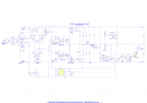
did you check DC protect, something wrong in your schema.
Regards
MANOJ
hi manoj ,i used sir kartino surodipo schematic the protection side from his ucd amp . he even has many videos of his many amps working.
i have seen the t5 and t6 are mixed up i have to swap them 😱🙁. thanks again sir manoj
Attachments
Last edited:
you have to have the eagle software version 9 and higher
here you go sir .
have fun 😀😀
thank you sooooo much
hi manoj ,i used sir kartino surodipo schematic the protection side from his ucd amp . he even has many videos of his many amps working.
i have seen the t5 and t6 are mixed up i have to swap them 😱🙁. thanks again sir manoj
hi Stewin
how are you today ?
are you edit your amp with this new schematic ?
can you share edited board files please ?
hi Stewin
how are you today ?
are you edit your amp with this new schematic ?
can you share edited board files please ?
hello all still working on the amp , i will post the edited version plus its smps i intead to use😉
I have been following this very interesting thread for a while. I have built many other types of amps and am interested in looking at this class D design as my first attempt at Class D. There are some questions I have about its design and component selection...
Why not use AD713 instead of TL074?
The PSU stage for the Opamp surely could be better and utilise a capacitance multiplier with a linear regulator (transistor + zener etc)?
Would using higher Opamp rail voltages improve Opamp performance in this circuit?
How critical is board layout for signal integrity?
Opamp choice is critical in regards to latching. Whenever you need to force an opamp to potentially act as a comparator, make sure the specs say: Latch-Up-Free Operation.
Incidentally I know AD712 latches badly, so that's a no.
Incidentally I know AD712 latches badly, so that's a no.
But the latest installment by stewin has a discrete comparator, so the other opamps may do.
i still use the tl074 , the amp is nice but if you are making it make sure you use bc337,bc327 and tl074.
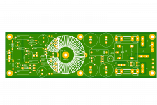
updates on my amp. firstly i rectified the transistor arrangement on the dcp section , then i removed the overcurrent protection and remained with the dc protect 😀 . (I should have used an optocupler at the ocp instead of the transistor😱. when i connected the ocp to the shutdown of the amp it had a bad noise interference.) the files below for the revised amp with only dcp
Attachments
-
200wt smd standard ver1.2 dc prtc.zip209.5 KB · Views: 190
-
200wt smd standard ver1.2 dc prtc all components full.pdf53.1 KB · Views: 196
-
200wt smd standard ver1.2 dc prtc pcb a4 full pcb full.pdf751.9 KB · Views: 203
-
200wt smd standard ver1.2 dc prtc schematic.pdf36.4 KB · Views: 252
-
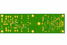 200wt smd standard ver1.2 dc prtc b.png99.4 KB · Views: 723
 -
 200wt smd standard ver1.2 dc prtc a.png131.7 KB · Views: 725
 -
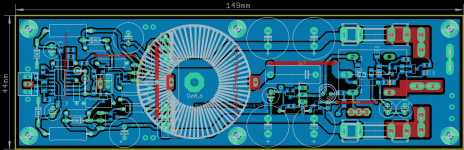 200wt smd standard ver1.2 dc prtc pcb.png206.6 KB · Views: 808
 -
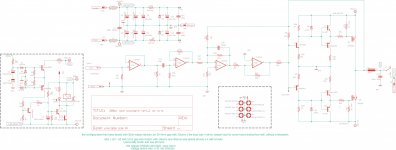 200wt smd standard ver1.2 dc prtc schematic.jpg693.1 KB · Views: 770
Last edited:
Thanks for the recommendations. BC327/337 are good for me as I have a lot of them. Where is the best place to get instructions on creating the choke? Which ferrite material can be used yellow/green/red?
I typically use Sprint Layout for boards so I will develop a new board using that tool. I am looking forward to getting into this while "working" from home! lol
Thanks again.
I typically use Sprint Layout for boards so I will develop a new board using that tool. I am looking forward to getting into this while "working" from home! lol
Thanks again.
Thanks for the recommendations. BC327/337 are good for me as I have a lot of them. Where is the best place to get instructions on creating the choke? Which ferrite material can be used yellow/green/red?
I typically use Sprint Layout for boards so I will develop a new board using that tool. I am looking forward to getting into this while "working" from home! lol
Thanks again.
use this original schematic by etgale . it works fine .as for output inductor use 22uh to 50uh . choose the best for you.
please use 9540 and 540 fets
much regards . please post photos of your build.
Attachments
i still use the tl074 , the amp is nice but if you are making it make sure you use bc337,bc327 and tl074.
updates on my amp. firstly i rectified the transistor arrangement on the dcp section , then i removed the overcurrent protection and remained with the dc protect 😀 . (I should have used an optocupler at the ocp instead of the transistor😱. when i connected the ocp to the shutdown of the amp it had a bad noise interference.) the files below for the revised amp with only dcp
hi mr Stewin
can you share OCP with optocupler please ?
i want add to schematic
thank you
i havent tried it but i think jlesters design will work
try this one posted by jlester
Opamp choice is critical in regards to latching. Whenever you need to force an opamp to potentially act as a comparator, make sure the specs say: Latch-Up-Free Operation.
Incidentally I know AD712 latches badly, so that's a no.
Hi Hlaford, I'm a bit late in replying to your comment but I just found this thread and found it extremely interesting. Can you please elaborate a bit about latch up free operation or point me to a source or link? I simply cannot find some useful info about this.
A relevant question, The op-amp TL074 has a 3 MHz unity bandwidth with a slew rate of 13V/V. Don't you think it will slow to respond to high amplitude, fast switching waveform from the output of the amplifier? Regards Vakas
Opamp choice is critical in regards to latching. Whenever you need to force an opamp to potentially act as a comparator, make sure the specs say: Latch-Up-Free Operation.
Incidentally I know AD712 latches badly, so that's a no.
hi please draw a schematic of lm311 using this schematic . thanks (hoping that lm311 is better than tlo74 in regards to latching)
https://www.diyaudio.com/forums/att...ltra-simple-class-switchingamp_189_page_1-jpg
https://www.diyaudio.com/forums/att...29439-ultra-simple-class-switchingamp_189-pdf
Last edited:
And I'm late to reply 🙂Hi Hlaford, I'm a bit late in replying to your comment but I just found this thread and found it extremely interesting. Can you please elaborate a bit about latch up free operation or point me to a source or link? I simply cannot find some useful info about this.
A relevant question, The op-amp TL074 has a 3 MHz unity bandwidth with a slew rate of 13V/V. Don't you think it will slow to respond to high amplitude, fast switching waveform from the output of the amplifier? Regards Vakas
Some op-amps go into a phase reversal when the common mode range at the inputs is violated. When it happens, the output goes hard to a (wrong) rail voltage, and if ever at all recovers from that condition too slow for the application at hand. Some parts simply give up the smoke. The manufacturers don't advertise it, except for the parts that don't latch.
There is a link to something about the common mode violations: https://www.edn.com/are-you-violating-your-op-amps-input-common-mode-range/
It is safe to say that whenever an opamp may turn into a comparator, you have a risk of latching.
When it latches there is no negative feedback, and the fireworks begin. Hopefully only fuses.
- Home
- Amplifiers
- Class D
- Ultra Simple Class D