you are absolutely right about straight lines and etc., but yes the system has to measured by the ear as well!
I don't want to measure music...I rather listen to it,
so if my ear tells me that something sounds better with a little more ripple I will stay with it, ....sound that I prefer always will come first! many may disagree with that opinion.
obviously, a perfect world would be when everything measures and sounds great, but not always like that.
When a ripply and noisy PSU is preferred by ear one can be almost sure that interpretation is lost or that other factors come to play in the foreground. I see such situations and often it is indeed other factors that are the culprit as it can not be that ripple in the audible range (!) makes stuff any better.
This reminds me of a single complaint about a DAC I once sold. The guy that bought it complained that although it sounded good he found the hum to be unbearable. It turned out that he had connected the DAC board to an AC filament winding 😀
Anyway my tip is to do CLC filtering with any of the uLDO regs and to use mains filtering in any case. Metal cases connected to PE and DC GND referenced to PE with 100 Ohm and a cap in parallel. Ferrite core around near the DC jack close to the device. Standard practice in good linear PSU design so to speak.
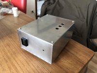
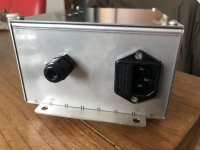
My latest attempt on a classic industrial looking PSU. One forgets stainless steel is a dog to work with unless one tries again after having forgotten.
This reminds me of a single complaint about a DAC I once sold. The guy that bought it complained that although it sounded good he found the hum to be unbearable. It turned out that he had connected the DAC board to an AC filament winding 😀
Anyway my tip is to do CLC filtering with any of the uLDO regs and to use mains filtering in any case. Metal cases connected to PE and DC GND referenced to PE with 100 Ohm and a cap in parallel. Ferrite core around near the DC jack close to the device. Standard practice in good linear PSU design so to speak.
My latest attempt on a classic industrial looking PSU. One forgets stainless steel is a dog to work with unless one tries again after having forgotten.
Attachments
Last edited:
I get your point and filament winding example 🙂,
I do CLC before and after regulators, I separate supplies as well, digital kept separate from analog and grounds and etc, ferrite cores as well.
i didn't mean to say the TPS7A4700 sounds bad, it sounds great no HUM 🙂,...but prefer the original Chinese (tweaked) concept with tl431,
I will build Peufeu's concept and give it a try.
OK, I asked if they were in 3 pin module format (like this) because in this format when there are input and output caps on the module, due to the high inductance of the ground pin, input HF noise goes straight through the input cap, it ignores the ground pin, goes straight through the output caps into the output, so it has 0dB PSRR above a few hundred kHz lol. I've measured a 3-pin module with the high-end TPS ultra-everything regulator on it, and the PSRR curve was exactly like that.

It's intriguing that these two regs sound different... Have you tried to check the power supply while the device plays music or signal? Maybe cap-couple it into the input of a preamp and FFT the result, or even listen to it...

Both 😀
Since input cap and output cap are joined at GND, and GND connected to pcb ground with the inductance of the pin, larger caps means lower PSRR... exactly the opposite of normal
Since input cap and output cap are joined at GND, and GND connected to pcb ground with the inductance of the pin, larger caps means lower PSRR... exactly the opposite of normal
The ones as sold by also much criticized LDOVR are fine AFAIK. I am surprised by the design errors by Ian, thought his designs were measured and tested....
Goes to show anyone human makes errors.
You bring me back to the simplest of tests and you are right. Of course I measured and tested with the device playing. The cap coupling is not done however. It are very marginal differences but many noticed the same so there is a pattern. Same when using ideal rectifiers, one can hear that at once...
Goes to show anyone human makes errors.
It's intriguing that these two regs sound different... Have you tried to check the power supply while the device plays music or signal? Maybe cap-couple it into the input of a preamp and FFT the result, or even listen to it...
You bring me back to the simplest of tests and you are right. Of course I measured and tested with the device playing. The cap coupling is not done however. It are very marginal differences but many noticed the same so there is a pattern. Same when using ideal rectifiers, one can hear that at once...
Last edited:
Maybe I do (although the idea is to keep anything else than DC far away) but I haven't found any of significance. The philosophy is to make PSU's as clean as possible with low output impedance, ample current reserve, low drop out, low heat generation and high efficiency. We call them 50 Hertz switchers.
Did you experience that in your designs or do I have to guess?
Did you experience that in your designs or do I have to guess?
Last edited:
I am fine with old-fashioned soft recovery diodes.
I don't need 6MHz charge pumps in my linear supply.
But then people also use 100kHz SMPS and Class D amps.
Personal tastes.
Patrick
I don't need 6MHz charge pumps in my linear supply.
But then people also use 100kHz SMPS and Class D amps.
Personal tastes.
Patrick
~Some build heat generating class A and effect generators 🙂
I haven't found any 6 MHz of significance in my power supplies (I use Schottky diodes mostly but built a few with LT4320) but I also use CLC filtering mostly. Like you I would not need 6 MHz garbage in my linear PSU's either and I suppose not many would want that. Are you sure it is a showstopping issue? I have used DAC chips with charge pumps and also was not able to find shocking stuff with my outdated test gear. Maybe some assumed problems are simply not problems and merely a predefined choice?
For performances sake I will remeasure just in case.
Last edited:
Compared to what? It is factors more noisy than suggested regs. It is good though and its cousin LT1764 is even 3A @ 0.34V dropout. I use the latter with good results, a relatively easy way to build a quite well performing 3A uLDO PSU with reasonable low noise and in some aspects superior to SMPS. TPS7A4700 and even more so the LT3045 are better but with either relaxed maximum current or voltage ratings.
So... the question is what voltage and current one needs and then choose a suitable regulator with best specs. Maybe we can (over)simplify the choice based on the needed output voltages/currents and look less at lowest noise. So till 15V 0.5A the LT3045, for output of max 20V at 1A the TPS7A4700 and for max 20V 3A the LT1764.... the company that manages to produce a 20V 3A 1 µV low noise TO220 device will be king of the hill.
So... the question is what voltage and current one needs and then choose a suitable regulator with best specs. Maybe we can (over)simplify the choice based on the needed output voltages/currents and look less at lowest noise. So till 15V 0.5A the LT3045, for output of max 20V at 1A the TPS7A4700 and for max 20V 3A the LT1764.... the company that manages to produce a 20V 3A 1 µV low noise TO220 device will be king of the hill.
Last edited:
I'll bet a beer that most audiophile "yultra low noise" regulators over 200mA are used to power raspberry pi's which have a switching DC-DC on the input, or something of the sort
Possibly but what if it the combination performs better than the RPI-SMPS combination? It will look ugly but less ugly than it was before 🙂 Of course I know exactly what you mean as I use my devices on such sources but still they outperform the old PSU's so all is good.
Last edited:
Interesting thread. I recently added an LT3042 to power thr 3v3 rail of a cheap dvd player dac chip. It originally is from an smps derived rail. No local regulation. I was surprised to hear if sounded worse to my ears. Lost lots of body and dynamics and seemingly lesser LF.
Maybe the smps 3v3 adds distortion that I like. Or maybe some other factor. But I will never know the reason as I can't measure and not sure if I want to.
So I blissfully remove the nice ldo and listen to the smps. Strange but true.!
Maybe the smps 3v3 adds distortion that I like. Or maybe some other factor. But I will never know the reason as I can't measure and not sure if I want to.
So I blissfully remove the nice ldo and listen to the smps. Strange but true.!
Possibly but what if it the combination performs better than the RPI-SMPS combination? It will look ugly but less ugly than it was before 🙂 Of course I know exactly what you mean as I use my devices on such sources but still they outperform the old PSU's so all is good.
...any experience with ADM7150 regulator?,
it seems to be easy implementation and the noise is quite low?
did anyone compare it soundwise with the above-mentioned already?
But I will never know the reason as I can't measure and not sure if I want to.
You answered your own question in a way. If a per definition noisy PSU is followed by an ultra low noise regulator and results are bad then something is simply not right. Normally the procedure is to test and measure any done change to verify what is done, at least when one uses standard scientific methods. Even a cheap used 20 MHz oscilloscope can be used for that (50 to 100 Euro).
It can not be that assumptions and testing by ear are the instruments to check DIY Audio and electronics. It is like driving in the dark at the wrong lane with no headlights and then blame the car when you hit a pole. You don't have a picture do you? My suspicion is the chosen point where you have connected it to GND is the cause or ... a GND loop of sorts.... that occur easily when adding a new power supply in an existing device.
@kropka235: no but I should try it I think. Contrary to the ones I have tried this one can be soldered by hand which is a very positive feature.
Last edited:
- Home
- Amplifiers
- Power Supplies
- ultra low noise psu from China